


Warning: Remember that the dust generated by the brake mechanisms may contain asbestos, which is extremely harmful to human health. Never blow off dust with compressed air or inhale it; wear a protective mask or respirator when servicing the mechanisms. Never use gasoline or petroleum-based solvents to wipe brake system components - use only branded cleaning agents or methyl alcohol!
1. The condition of the brake system components, in addition to the regular checks specified in the routine maintenance schedule, must be assessed every time the wheels are removed or when signs of a malfunction in the brake system occur.
2. The following symptoms may indicate a faulty brake component:
- a) When braking, the car loses directional stability (there is a pull to one side);
- b) When braking, the brakes make a squealing or squeaking noise;
- c) The foot brake pedal travel increases excessively;
- d) There are traces of brake fluid leakage (usually on the inner surface of wheel rims and tires).
3. Loosen the wheel bolts.
4. Jack up and place the vehicle on supports or lift it on a lift.
5. Remove the wheels.
Disc brakes
6. The disc brake caliper is equipped with two brake pads (internal and external). When the wheel is removed, sufficient access is available for inspection and testing of the outer brake pad. The residual thickness of the friction lining of the inner pad is assessed visually through the inspection window of the caliper (see accompanying illustration) after removing the wheel.
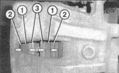
14.6. Checking the residual thickness of the brake shoe linings: 1. Brake linings; 2. Metallic backings of the outer and inner brake pads; 3. Brake disc
7. The measurement of the residual size of the brake shoe linings is carried out using a ruler. Lining thickness (excluding the thickness of the metal substrate) must be at least 2 mm. If the linings are worn beyond the permissible limit, it is necessary to carry out a comprehensive replacement of the brake pads.
Attention: All brake pads on one axle must be replaced at the same time, even if only one of them has reached its wear limit!
8. If there is any doubt about the condition of the linings or there is a need for a more detailed inspection of the brake pads, remove the calipers) and take out the pads for a more detailed examination (see Chapter 9).
9. After the pads have been removed from the caliper, clean them with a special agent and check the remaining thickness of the linings with a ruler or a caliper equipped with a vernier.
10. Measure the thickness of the brake discs with a micrometer. Compare the measurement results with the standard requirements (see Specifications)If the thickness of any of the discs is outside the acceptable range, replace it (see Chapter 9). If the disk thickness is normal, check its general condition. Pay attention to such defects as deep scratches, grooves, scuffs, traces of overheating, etc., if necessary, remove the disk and give it for turning (see Chapter 9).
11. Before reinstalling the wheels, inspect all brake lines for signs of damage, wear, degradation due to aging of the material, signs of leaks, bends, twists and other deformations (especially near the connection points of flexible brake hoses to the brake calipers). Check that the hose clamps are securely fastened. Make sure that none of the brake hoses come into contact with sharp corners of adjacent body parts, exhaust system components, or suspension components (at any steering wheel position). If necessary, make appropriate repairs or adjust the route of the lines. Replace defective components (see Chapter 9).
12. There is a practical way to calculate the brake pad life to plan their timely replacement. When operating a vehicle in difficult conditions (urban cycle, mountainous terrain, etc.) for front disc brakes, lining wear of 1 mm approximately corresponds to a mileage of 1000 km. Then, for example, with a thickness of 5 mm (excluding the thickness of the metal substrate) the brake lining will last at least another 3,000 km. Under normal operating conditions, the linings last much longer.
13. Once the check is complete, reinstall the wheels, paying attention to the direction of the tread pattern, tighten the wheel bolts, lower the vehicle and tighten the bolts diagonally to the required torque (110 Nm).
Drum brakes
14. To check the thickness of the brake linings of the rear drum brake mechanisms, it is necessary to remove the rubber plugs from the inspection holes (see accompanying illustration). Using a portable lamp, illuminate the pads through a special hole and assess the remaining thickness of the brake pads - pad thickness (excluding the thickness of the metal substrate) must be at least 1 mm.
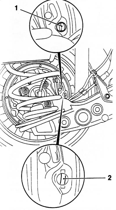
14.14. Inspection hole (1) for checking the residual thickness of the brake shoes of the rear drum brake mechanism
15. If there is any doubt about the condition of the linings or there is a need for a more detailed inspection of the brake shoes, remove the brake drums and take out the shoes for a more detailed examination (see Chapter 9).
16. If cracks, signs of wear, polished to a shine or oily areas of the linings are detected, the brake pads must be replaced.
Attention: All brake pads on one axle must be replaced at the same time, even if only one of them has reached its wear limit!
17. Every time you check the brake shoes, also check the condition of the brake drums. Try not to inhale asbestos-containing brake dust - carefully wipe the inner surfaces of the brake drum with a clean rag soaked in methyl alcohol.
18. Inspect the working surface of the drum for cracks, burrs, traces of overheating and other damage. If the defects cannot be removed by treating the surface with fine-grained sandpaper, the drum should be given to a car service workshop for turning or replaced.
19. Pull back the protective caps of the wheel brake cylinder (see accompanying illustration) and check for brake fluid underneath them. If a leak is found, replace the wheel cylinder.
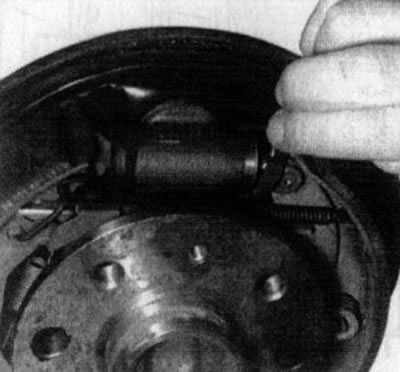
14.19. Checking brake cylinders for brake fluid leaks
20. Repeat the procedure for the opposite brake components. Reinstall the shoes and drums (see Chapter 9), secure the wheels and lower the car to the ground.
Vacuum booster
21. The proper functioning of the brake booster is checked from the driver's seat.
22. With the foot brake pedal fully depressed, start the engine - the pedal should still fall a little.
23. With the engine running, press the foot brake pedal several times. The pedal travel should remain constant.
24. Press the pedal, turn off the engine and continue to hold the pedal pressed for about another 30 seconds, during which time it should neither fall lower nor rise.
25. Start the engine again, let it run for a minute, then turn it off again. Press the pedal firmly several times again - the stroke should decrease with each stroke.
26. If the result of the described check is negative, the brake booster servo drive must be replaced (see Chapter 9).
Parking brake
27. The parking brake is applied using a lever installed between the front seats (see Chapter "Controls and operating techniques"). The parking brake mechanism is checked for proper operation with the vehicle fully suspended - the wheels must be at least 5 cm above the ground. Before starting work, make sure the vehicle is securely fixed.
28. Release the parking lever completely and manually check the freedom of rotation of the wheels.
29. Raise the parking brake lever 3 clicks - the wheel should brake immediately when free to rotate, but should turn with difficulty when force is applied. Braking of both wheels should be done with the same force.
30. If the above conditions are not met, make the necessary adjustments (see Chapter 9).
31. Alternatively, the parking brake can be checked for proper operation by parking the vehicle on a slope and holding it still with the parking brake with the gearbox in neutral. If the brake does not hold the vehicle when the lever is pulled the required number of clicks, it is necessary to adjust it (see Chapter 9).
Visitor comments