
Attention: When equipping a car with head airbags, strictly follow the safety precautions (see Chapter 10, Section 11)!
Corsa C, 3-door hatchback
1. Disconnect the wires and insulate the battery terminals. Wait at least 1 minute for the SRS battery pack capacitor to fully discharge.
2. Remove the rear side trim (see Section 45).
3. Open the front door and, if necessary, separate the door seals from the B-pillar. On models equipped with head airbags, use a plastic wedge to pry off the service cover on the trim of the B-pillar (see resist. illustration) and carefully separate it by gradually moving the wedge along the perimeter of the lid.
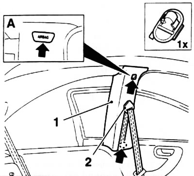
44.3. Finishing (1) B-pillars (3 door hatchback) - arrow (A) head airbag service cover indicated, lower arrow indicates trim retainer: 2. Front seat belt upper anchor brace
4. Remove the upper seat belt anchor from the B-pillar (see Section 50), using a plastic wedge, press out the lower trim retainer (see illustration 44.3) and take it off.
5. Install in reverse order of removal, making sure the inside edge of the seal is on top of the trim.
Corsa C, 5-door hatchback
Top finish
6. Disconnect the wires and insulate the battery terminals. Wait at least 1 minute for the SRS battery pack capacitor to fully discharge.
7. Open the front and rear doors and, if necessary, separate the door seals from the B-pillar. On models equipped with head airbags, use a plastic wedge to pry off the service cover on the trim of the B-pillar (see resist. illustration) and carefully separate it by gradually moving the wedge along the perimeter of the lid.
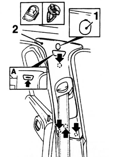
44.7. Removing the top trim (2) B-pillars (5 door hatchback) - the arrows indicate the clamps: 1. Decorative cap; A. Head airbag service cover
8. Using a plastic wedge, separate the decorative plug at the top of the trim (see illustration 44.7) and remove the fixing screw underneath. Then insert the plastic wedge under the trim and wring out the 4 latches.
9. Remove glove box from sill trim panel (see Section 42).
10. Disconnect the lower seat belt anchor from the front seat (see Section 50), pull the seat belt out of the top anchor height adjuster and remove the top trim section from the B-pillar.
11. Install in the reverse order of removal, making sure that the inner edge of the seal is on top of the trim. Tighten the seat belt fastening screw with the required force, having previously lubricated its threads with a fixing compound. Check that the webbing of the belt is not twisted and that it can be wound freely by the drum. Check the belt for proper functioning.
Bottom trim
12. Remove the top finishing of a rack In (see above).
13. Using a plastic wedge, wring out the latches of the lower trim (see resist. illustration) and separate it from the B-pillar.
44.13. Removing the bottom trim (1) B-pillars (5 door hatchback) - the arrows indicate the clamps: 2. The edge of the fastening of the trim to the threshold
14. Using a plastic wedge, disconnect the lower edge of the B-pillar trim from the sill trim panel (see illustration 44.13).
15. Install in the reverse order of removal, making sure that the inner edge of the seal is on top of the trim.
Combo Models
16. Move the front seat forward until it stops.
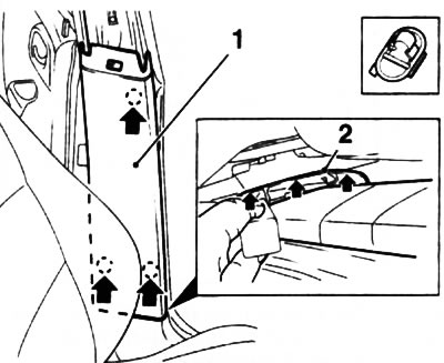
17. Turn out the fixing screw and insert under the bottom trim (arrow A) plastic wedge, wring out 2 latches and separate the lower trim from the B-pillar (see resist. illustration).
44.17. Removing the bottom trim (2) B-pillars (combo models) - the arrows indicate the clamps: 1. Mounting screw; 3. Upper B-pillar trim; 4. Clips for attaching the bottom trim to the top
18. Squeeze out the 2 upper latches (see illustration 44.17) and separate the bottom trim section from the top. Remove the lower trim from the B-pillar.
19. Remove the upper seat belt anchor from the B-pillar (see Section 50), wring out the 4 clips with a plastic wedge and remove the upper trim section from the B-pillar.
20. Installation is carried out in the reverse order of removal, while the lower edge of the upper trim of the B-pillar should go under the upper edge of the lower trim (see illustration 44.17). Tighten the seat belt anchor to the correct torque. Check that the webbing of the belt is not twisted and that it can be wound freely by the drum. Check if the belt is working properly (see chapter «Controls and methods of operation»).
Meriva Models
Top finish
21. Disconnect the wires and insulate the battery terminals. Wait at least 1 minute for the SRS battery pack capacitor to fully discharge.
22. Open the front and rear doors and, if necessary, separate the door seals from the B-pillar. On models equipped with head airbags, pry off the service cover on the B-pillar trim with a plastic wedge, carefully separate it and remove the fixing screw.
23. Squeeze 4 latches in the area of the device for adjusting the height of the upper anchor and separate the upper trim from the B-pillar.
24. Squeeze the tabs (see resist. illustration) and separate the upper B-pillar trim from the lower one.
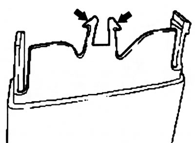
44.24. Fasteners (indicated by arrows) B-pillar top and bottom trim fixings (Meriva models)
25. Disconnect the lower seat belt anchor from the front seat (see Section 50), pull the seat belt out of the top anchor and remove the top trim section from the B-pillar.
26. Installation is in the reverse order of removal, while making sure that the inner edge of the seal is on top of the trim. Tighten the seat belt fastening screw with the required force, having previously lubricated its threads with a fixing compound. Check that the webbing of the belt is not twisted and that it can be wound freely by the drum. Check if the belt is working properly (see chapter «Controls and methods of operation»).
Bottom trim
27. Remove the top trim of the B-pillar (see above).
28. Using a plastic wedge, wring out the clamps of the lower trim of the B-pillar (see illustration 44.28, A), insert a screwdriver from the inside of the trim and push out the support pin (see illustration 44.28, B) seat belt winder.
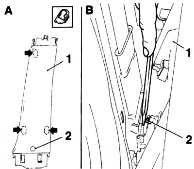
44.28. Fasteners (indicated by arrows) bottom trim fixings (1) B-pillars (Meriva models): 2. Support pin
29. Remove the sill trim panel along with the lower B-pillar trim section (see Section 42).
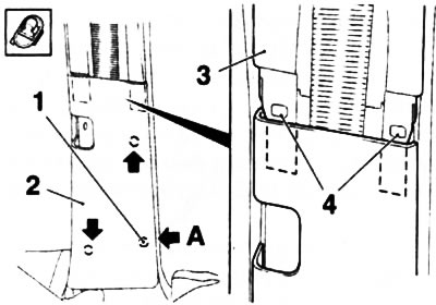
30. Remove the insulating pad from the back of the sill trim panel (see resist. illustration), pry out the 2 latches with a screwdriver and separate the B-pillar lower trim.
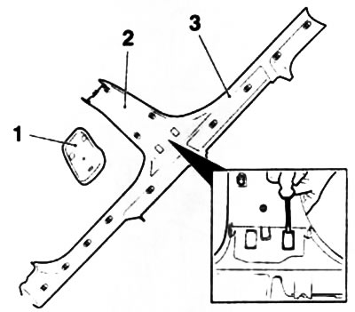
44.30. Removing the bottom trim (2) pillars B from the panel (3) threshold finishes (Meriva models): 1. Insulating pad
31. Installation is in the reverse order of removal, while making sure that the inner edge of the seal is on top of the trim. Check the condition of the clamps, replace if necessary.
Visitor comments