
Remember that gasoline is a highly flammable liquid! Observe all applicable fire safety precautions when working on power system components. Do not smoke! Do not approach the place of work with an open flame or carrying an unprotected lampshade! Do not service the system in rooms equipped with natural gas-fired heaters equipped with a pilot flame (such as water heaters and clothes dryers). Do not forget that gasoline is classified as a carcinogen, i.e., substances that contribute to the development of cancer! Try to prevent fuel from getting into open areas of the body - use rubber protective gloves, in case of accidental unforeseen contact with fuel, wash your hands thoroughly with warm water and soap. Clean up spilled fuel immediately and do not store fuel-soaked rags near open flames. Remember that the fuel injection system of models equipped with fuel injection is constantly under pressure. Relieve any residual pressure in the system before attempting to disconnect fuel lines. Wear safety goggles when servicing power system components. Keep a class B fire extinguisher handy at all times!
The following describes the procedures for removing and installing the throttle body on 1.2 and 1.4L engines with 45 and 60 hp. respectively.
Throttle Body Assembly Components
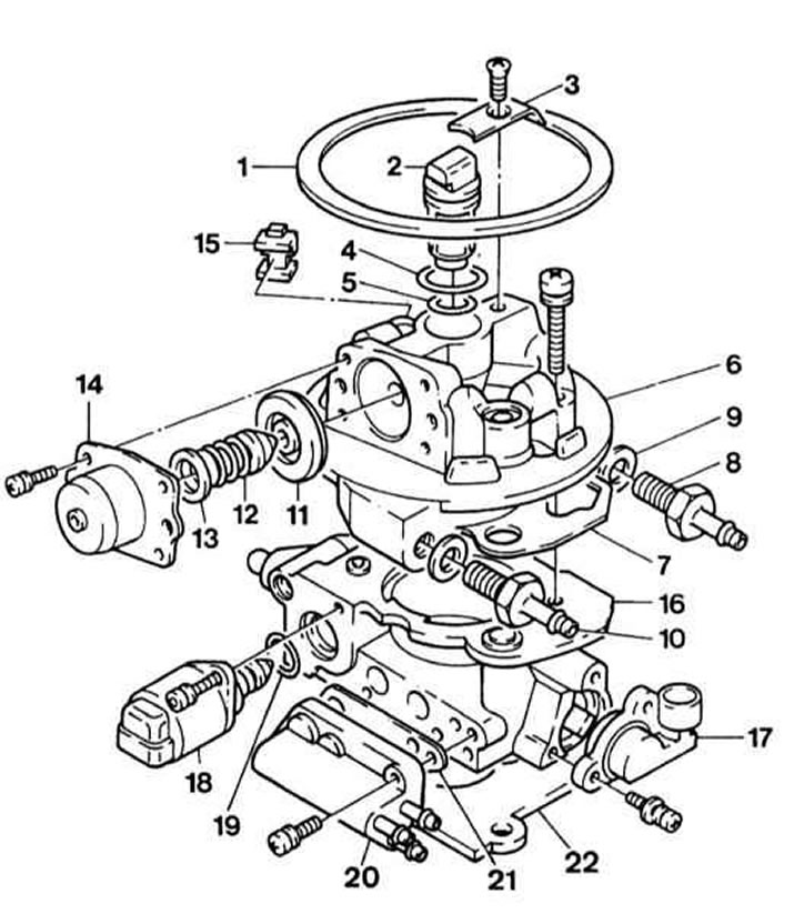
1 - Seal of the preliminary chamber
2 - Injector
3 - Holder
4 — the Top sealing ring
5 - Lower sealing ring
6 - Upper part of the body
7 - Seal the top
8 - Fuel supply fitting
9 — Consolidation of the union of supply of fuel
10 - Fuel return fitting
11 - Diaphragm fuel pressure regulator
12 - Spring fuel pressure regulator
13 — a saddle of a spring of a regulator of pressure of fuel
14 - Fuel pressure regulator cover
15 — Rubber gland
16 - Throttle body
17 - Throttle valve potentiometer (TPS)
18 - Stepper e / motor of the idle speed control system
19 - O-ring
20 - Flange
21 - Flange seal
22 - Throttle body seal
Removing
1. Relieve the fuel pressure in the system.
2. Disconnect the negative cable from the battery.
3. Disconnect the ventilation hose from the prechamber.
4. Disconnect the vacuum hose at the rear of the throttle body, at the prechamber.
5. Remove the prechamber using a Phillips screwdriver and move the air hose aside (see Section Removal and installation of components of an inlet air path).
6. Tape all throttle body connectors and disconnect them.
7. Mark the fuel lines with tape and disconnect them from the fittings, cut off the clamps if necessary.
Place a rag beforehand and wipe off the escaping fuel.
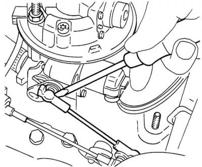
8. Press the drive rod away from the throttle lever with a screwdriver. Remove the locking pin first.
Depressing drive rod
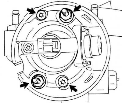
9. Give two nuts of fastening of the case of a throttle and two bolts of fastening of its top part.
Fasteners of the upper part of the throttle body
10. Remove the top. Remove sealant residue and clean mating surfaces.
Installation
1. Install the top with a new gasket.
2. Lubricate the threads of the bolts and nuts with a hardening sealant, for example, OPEL-15 10 177.
3. Tighten the nuts securing the throttle body with force 22 Nm and bolts for fastening its upper part with a force 6 Nm.
4. Further installation is carried out in the reverse order to the dismantling of the components. Torque the prechamber fasteners 4 Nm.
5. Start the engine and check the fittings for leaks.
Visitor comments