OpelBook.ru
Cars AvtoVAZ Cars Mitsubishi Cars BMW Cars Mercedes Cars Nissan Cars Toyota Cars Chevrolet
English Русский
Български
Беларускі
Український
Српски
Hrvatski
Română
Polski
Slovenský
Magyar
 |  Sitemap  |  Contacts  |    


Main Astra Corsa Insignia Kadett Omega Vectra Zafira Others Articles
Astra F (1991-1998, petrol) Astra G (1998-2004, petrol) Astra G (1998-2004) Astra H (2004-2009) Astra J (2009-2015, petrol)
  • Main
  • Astra
  • Astra G
  • Chassis
  • Brake system
  • Removal and installation the master brake cylinder

Removal and installation the master brake cylinder (Opel Astra G)

            0

Contents: Removal ⬇ Installation ⬇
A failed brake master cylinder must be replaced. Manufacturers do not recommend attempting to perform a refurbishment of the brake master cylinder.


Removal


The brake master cylinder is located in the engine compartment of the vehicle and is attached to the brake booster assembly.

1. Press the foot brake pedal several times to release any residual pressure in the system zafira models remove the plastic cover at the rear of the engine compartment.

2. Pump out as much of the fluid as possible from the master cylinder reservoir (use a syringe or a rubber bulb).

3. Place rags under the fittings and have caps or plastic bags available to plug the open ends of the brake lines to prevent dirt from entering the system.

Brake fluid is an aggressive chemical compound and when in contact with body panels it destroys the paintwork. Before starting the procedure, cover the fenders and the front panel of the car with special covers or just old blankets.


4. If equipped, disconnect the electrical wiring of the brake fluid level switch sensor from the brake master cylinder reservoir.

(Text copied from this portal: «opelbook.ru»)

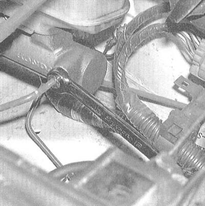
5. Loosen the nuts of the union assemblies connecting the brake lines to the master cylinder. To avoid rounding the splines of the nuts, loosen them using a special open-end wrench with a slotted head. Pulling slightly outward, separate the brake lines from the unions of the master cylinder. Immediately plug the open ends of the tubes.


5. Loosen the nuts of the union assemblies connecting the brake lines to the master cylinder. To…


6. Disconnect the clutch hydraulic line tube from the master cylinder reservoir - immediately plug the open end of the tube.

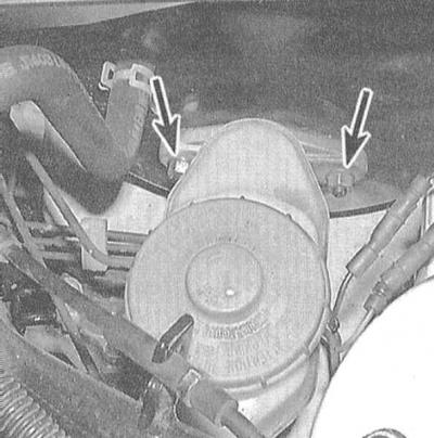
7. Loosen the two retaining nuts and separate the master cylinder from the brake booster assembly. Remove the cylinder from its retaining studs and lift it out of the engine bay, being careful not to spill the hydraulic fluid filling the cylinder onto the painted body panels. Remove the sealing gasket.

7. Loosen the two retaining nuts and separate the master cylinder from the brake booster assembly.…


8. If necessary, carefully pry the clamps with a screwdriver, release them and remove the brake fluid reservoir from the master cylinder assembly. Remove the reservoir seat bushings from the holes in the cylinder - the bushings must be replaced without fail.

Installation


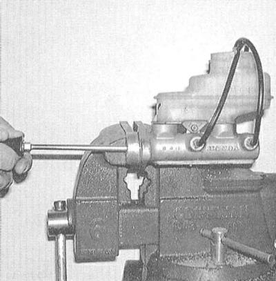
1. Before installation, the new brake master cylinder must be bled on a workbench. For convenience, clamp the cylinder mounting flange in a vice with soft jaws. Then you will have to simultaneously manipulate the piston in the cylinder and observe the flow of brake fluid pushed out through the outlet fitting. Install the brake fluid reservoir on the cylinder - do not forget to replace the bushings.


2. Connect a pair of tubes from a special bleeding kit to the master cylinder outlet fittings (ask in car accessories stores).

2. Connect a pair of tubes from a special bleeding kit to the master cylinder outlet fittings (ask…


3. Fill the reservoir with fresh brake fluid of the required grade (see Chapter Routine maintenance).

4. Slowly push the pistons into the cylinder (it will be most convenient to use a large Phillips-head screwdriver), - air should start to exit the pump chambers into the reservoir. It is important that the ends of both tubes are completely immersed in the brake fluid in the reservoir to eliminate the possibility of it being sucked back into the cylinder when the pistons are released.

5. Continue pumping until the liquid being pushed out through the tubes is completely free of air bubbles.

6. Disconnect the tubes one by one, immediately sealing the open ends of the fittings. Close the master cylinder reservoir with a lid.

7. Place the brake master cylinder on the studs on the vacuum booster assembly (don't forget to replace the sealing gasket) and, for now only by hand, tighten the fastening nuts.

8. Screw the brake line nipples into the cylinder. Since the cylinder is not yet firmly secured, its position can be adjusted slightly to make it easier to screw in the nipples - try not to strip the threads.


9. Tighten the brake master cylinder mounting nuts to the required torque, then tighten the nipple connections securely.

10. Fill the brake master cylinder reservoir with fresh brake fluid and bleed the hydraulic system (see Bleeding the brake system). For bleeding the master cylinder on a car (if you haven't done it on the workbench) you will need an assistant to operate the foot brake pedal. Ask the assistant to press the pedal several times, then lock it in the lower position. Loosen the union nut, releasing the mixture of air and brake fluid from the cylinder. Repeat the procedure until the fluid being pushed out is completely free of air bubbles. Proceed in a similar manner to bleed the second union.

Keep a clean rag handy to immediately remove any traces of brake fluid that gets on painted body surfaces.


11. Before operating the vehicle, make sure that the brakes are functioning properly.


This article is available at russian, bulgarian, belarusian, ukrainian, serbian, croatian, romanian, polish, slovak, hungarian
Checking the article: Pavlovsky Nikolay

Share information:

Previous articles
Opel Astra G: Brake system
Next articles

Removal, maintenance and installation of wheel cylinders of drum brake mechanisms of rear wheels
Removal, repair and installation of rear wheel disc brake calipers
Removal, repair and installation of front wheel disc brake calipers
Removal, inspection and installation of the brake drum
Checking the condition, removing and installing the brake disc
Replacing the shoes of the rear wheel drum brake mechanisms
Removal and installation the foot brake pedal
Checking the proper functioning/tightness, removing and installing the brake booster assembly
Removal, checking the correct operation and installation of the brake booster check valve
Removal and installation the brake booster servo vacuum pump (diesel models)
Checking the proper functioning of the brake booster servo vacuum pump (diesel models)
Adjusting the parking brake drive


See similar ones from other Opel car manuals:
▶ Master brake cylinder Opel Corsa C (2000-2006, petrol)
▶ Replacing the master brake cylinder Opel Insignia A (2008-2017)
▶ Removal and installation the brake master cylinder Opel Kadett E (1984-1995)
▶ Master Brake Cylinder — Removal and Installation Opel Omega B (1993-1999)
▶ Master brake cylinder Opel Vectra B (1995-2002, petrol)
Link to this page in different formats

Visitor comments


No comments yet


How much will 18 + 21 =


Astra J (2009-2015, petrol) 
  • General information
  • Vehicle device
  • User manual
  • Faults en route
  • Maintenance
  • Power unit
  • Engine repair
  • Cooling and lubrication system
  • Engine power system
  • Exhaust system
  • Transmission
  • Clutch
  • Car gearbox
  • Drive shafts
  • Chassis
  • Front suspension
  • Rear suspension
  • Steering
  • Brake system
  • Wheels and tires
  • Body
  • Exterior
  • Interior
  • Doors and windows
  • Body Care
  • Heating and air conditioning
  • Security systems
  • Electrical equipment
  • Equipment and devices
  • Lighting and signaling
  • Power devices
  • Electrical circuits
Astra H (2004-2009) 
  • General information
  • Introduction to the guide
  • Troubleshooting
  • User manual
  • Maintenance
  • Power unit
  • Engine repair
  • Cooling and heating
  • Power and exhaust system
  • Ignition system
  • Launch and charge system
  • Transmission
  • Mechanical gearbox
  • Automatic gearbox
  • Drive shafts
  • Chassis
  • Brake system
  • Car suspension
  • Steering
  • Body
  • Interior
  • Exterior
  • Electrical equipment
  • Equipment and devices
  • Electrical circuits
Astra G (1998-2004) 
  • General information
  • Introduction to manual
  • User manual
  • Maintenance
  • Power unit
  • SOHC gasoline engines
  • DOHC gasoline engines
  • Diesel engines 1.7 and 2.0
  • Engine repair
  • Cooling system
  • Supply system
  • Injection system (gasoline)
  • Injection system (diesel)
  • Exhaust system
  • Charge and launch system
  • Ignition system (gasoline)
  • Preheat system (diesel)
  • Transmission
  • Manual gearbox
  • Automatic gearbox
  • Clutch
  • Drive shafts
  • Chassis
  • Brake system
  • Wheel suspension
  • Steering
  • Body
  • Exterior
  • Interior
  • Doors and windows
  • Ventilation and heating
  • Electrical equipment
  • Equipment and devices
  • Electrical circuits
Astra G (1998-2004, petrol) 
  • General information
  • User manual
  • Car care
  • Maintenance
  • Power unit
  • Single shaft engines
  • Twin shaft engines
  • Engine repair
  • Cooling and heating
  • Fuel and exhaust systems
  • Starting and charging system
  • Ignition system
  • Transmission
  • Clutch
  • Mechanical gearbox
  • Automatic gearbox
  • Drive shafts
  • Chassis
  • Brake system
  • Car suspension
  • Steering
  • Body
  • Interior
  • Exterior
  • Electrical equipment
  • Equipment and devices
  • Wiring diagrams Opel Astra
  • Wiring diagrams Opel Zafira
Astra F (1991-1998, petrol) 
  • General information
  • Maintenance
  • Power unit
  • Engine in car
  • Engine removed
  • Cooling system
  • Heating and ventilation
  • Fuel supply (carburetor)
  • Fuel supply (injector)
  • Emission control
  • Ignition system
  • Transmission
  • Clutch
  • Mechanical gearbox
  • Automatic gearbox
  • Drive shafts
  • Chassis
  • Brake system
  • Car suspension
  • Steering
  • Body
  • Exterior
  • Interior
  • Electrical equipment
  • Equipment and devices
  • Electrical circuits
OpelBook.ru © 2017–2026 · Mobile version · · Sitemap: EN BG BY UA RS HR RO PL SK HU · Feedback · Site search
Astra F, petrol · Astra G, petrol · Astra G · Astra H · Astra J, petrol · Corsa B · Corsa C, petrol · Corsa C · Insignia A · Kadett D · Kadett E · Omega A · Omega B · Omega B2 · Vectra A, petrol · Vectra A · Vectra B, petrol · Vectra B · Vectra C · Zafira A, petrol · Frontera A, petrol · Frontera B · Ascona C · Vivaro A ·
We want your visit to be comfortable 🤝! We use cookies 🍪 to make that happen.