OpelBook.ru
Cars AvtoVAZ Cars Mitsubishi Cars BMW Cars Mercedes Cars Nissan Cars Toyota Cars Chevrolet
English Русский
Български
Беларускі
Український
Српски
Hrvatski
Română
Polski
Slovenský
Magyar
 |  Sitemap  |  Contacts  |    


Main Astra Corsa Insignia Kadett Omega Vectra Zafira Others Articles
Astra F (1991-1998, petrol) Astra G (1998-2004, petrol) Astra G (1998-2004) Astra H (2004-2009) Astra J (2009-2015, petrol)
  • Main
  • Astra
  • Astra G
  • Chassis
  • Brake system
  • Replacing the shoes of the rear wheel drum brake mechanisms

Replacing the shoes of the rear wheel drum brake mechanisms (Opel Astra G)

            0

The shoes must be replaced simultaneously on both brake mechanisms. Remember that the dust generated during operation of the brake mechanisms may contain asbestos, which is extremely harmful to human health. Never blow off dust with compressed air or inhale it - wear a protective mask or respirator when servicing the mechanisms. Never use gasoline or petroleum-based solvents to wipe the brake system components - use only branded cleaning agents or methyl alcohol!


At the same time as replacing the brake shoes, their tension and guide springs must also be replaced, as they stretch/sag over time as a result of constant cyclic mechanical and thermal loads, ceasing to develop the required force, which leads to the brakes seizing and accelerated wear of the drums.


It is correct to disassemble the brake mechanisms one by one; if necessary, the assembled mechanism can be used as a sample when assembling the dismantled one.


1. Remove the rear brake drum (see Removal, inspection and installation of the brake drum).

2. Sweep away any dust that has accumulated on the surfaces of the brake components (see warning at the beginning).

3. Measure the thickness of the friction linings of the shoes in several places. If the result of at least one of the measurements exceeds the maximum permissible value (see Specifications), all four shoes must be replaced.

4. Oily shoes must be replaced without fail - first eliminate the cause of the leak.

5. Try to remember the order of installation of the brake mechanism components - it would be more correct to make a sketch.


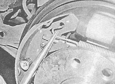
6. Disconnect and remove the upper tension spring.

7. Remove the holder and disconnect the adjusting lever assembly with its spring.
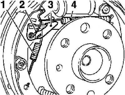
1 — Adjusting lever spring

1 — Adjusting lever spring

2 - Holder

3 — Adjustment lever

4 - Upper tension spring


8. Slightly spread the upper ends of the shoes apart and remove the adjusting expansion bar installed between them.
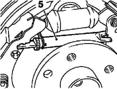
8. Slightly spread the upper ends of the shoes apart and remove the adjusting expansion bar…


9. Using a special device KM-346 or suitable pliers, turn the plates of the shoe guide spring holders so that the latter are released.
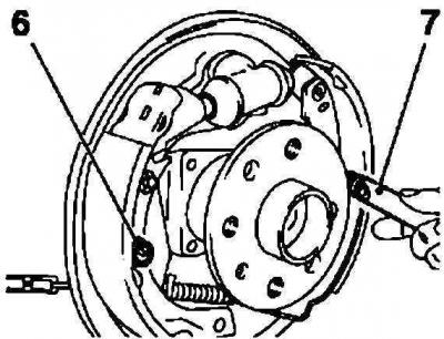
9. Using a special device KM-346 or suitable pliers, turn the plates of the shoe guide spring…


10. Disconnect the lower tension spring (9) from the rear shoe and remove it together with the front shoe (8).
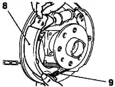


10. Disconnect the lower tension spring (9) from the rear shoe and remove it together with the…


11. Remove the rear shoe (10) from the anchor pin and disconnect it from the parking brake drive cable (11).
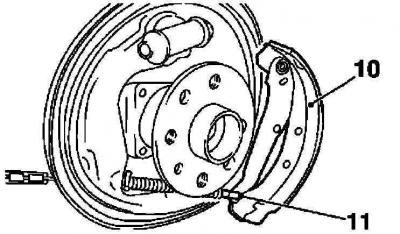
11. Remove the rear shoe (10) from the anchor pin and disconnect it from the parking brake drive…


12. Do not press the foot brake pedal with the brake shoes removed - for reliability, tighten the wheel cylinder pistons with a wire or plastic bandage.
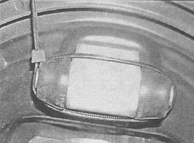
12. Do not press the foot brake pedal with the brake shoes removed - for reliability, tighten the…


13. If both brake mechanisms are disassembled at the same time, try not to mix up their components - the adjustment strips of the right and left mechanisms are marked with the letters L and R, respectively. The other parts of the left brake mechanism have colored marks, the right - silver.
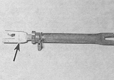


13. If both brake mechanisms are disassembled at the same time, try not to mix up their components…


14. Disassemble and clean the adjusting bar, lubricate the rod threads with silicone grease.

15. Check the condition of the tension springs. Corroded and stretched springs must be replaced.

Installing weak springs may result in brake lockup!


16. If necessary, transfer the parking brake actuator lever to the new shoe. The lever is riveted to the shoe or secured with a pin - the rivet should be drilled out. It may also be necessary to transfer the adjusting lever axle with the lock from the old shoe to the new one.
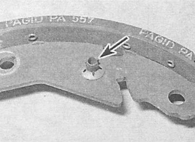
16. If necessary, transfer the parking brake actuator lever to the new shoe. The lever is riveted…


17. Remove the rubber boots from the wheel cylinder and inspect it for signs of developing leaks. Check the freedom of movement of both pistons, if necessary, carry out the appropriate restorative repairs (see Removal, repair and installation of front wheel disc brake calipers).
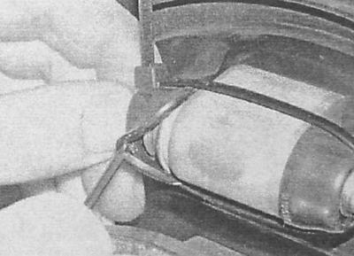


17. Remove the rubber boots from the wheel cylinder and inspect it for signs of developing leaks.…


18. Before installation, clean the brake shield. Lubricate the surfaces of the shield that come into contact with the moving components of the brake mechanism, as well as the pistons of the wheel cylinder, with high-temperature grease - try not to let the grease get on the friction linings.

19. Hook the end of the handbrake cable onto the hook on the shoe lever, making sure the cable fits into the guide on the brake shield. Install the rear shoe onto the brake shield.
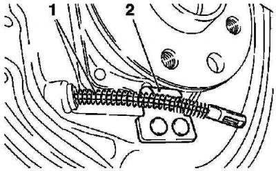
19. Hook the end of the handbrake cable onto the hook on the shoe lever, making sure the cable fits…


20. Install the anchor pin and rear shoe guide spring and secure the components with the holder.

21. Connect the lower tension spring to the rear shoe, then hook the front shoe onto it and install the latter in its regular place, engaging it with the guide.
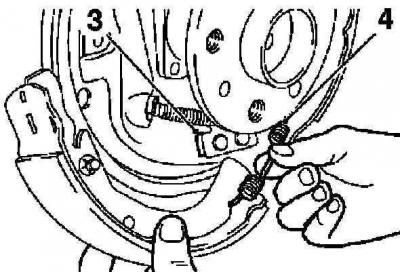


3 - Guide

3 - Guide

4 - Lower tension spring


22. Install the guide spring and secure it with the holder.
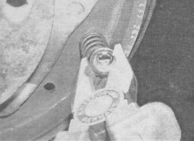
22. Install the guide spring and secure it with the holder.


23. Screw the threaded rod into the forked part of the adjusting expansion bar until it stops, shortening the latter to the limit. Turn the toothed wheel half a turn and check its freedom of rotation.
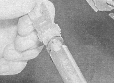
23. Screw the threaded rod into the forked part of the adjusting expansion bar until it stops,…


24. Place the bar between the shoes, with the long end facing the rear shoe.
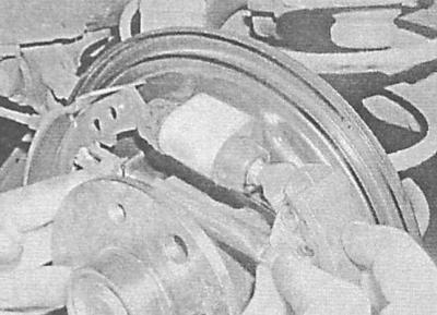


24. Place the bar between the shoes, with the long end facing the rear shoe.


25. Hook the lever of the adjustment mechanism onto the toothed wheel of the ratchet mechanism of the expansion bar.

25. Hook the lever of the adjustment mechanism onto the toothed wheel of the ratchet mechanism of…


26. Then place the lever on the axle and fix it in this position with the holder.
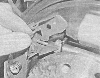
26. Then place the lever on the axle and fix it in this position with the holder.


27. Remove the piping from the wheel cylinder pistons. Make sure the shoes are correctly aligned with the pistons and install the upper tension spring.


A - Connecting the upper tension spring to the rear shoe

B - Connecting the upper tension spring to the front shoe

A.
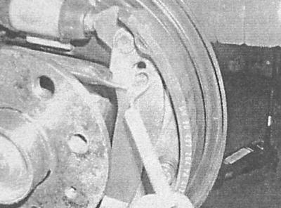
B - Connecting the upper tension spring to the front shoe


B.
B - Connecting the upper tension spring to the front shoe


28. Install the adjusting mechanism spring.
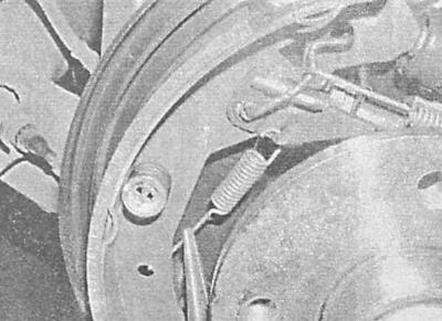
28. Install the adjusting mechanism spring.


29. Make sure that the parking brake actuator lever locking pin rests against the shoe rib and install the brake drum in place (see Removal, inspection and installation of the brake drum).

30. Proceed in a similar manner to service the second brake mechanism,

31. After installing both drums, with the parking brake fully released, press the foot brake pedal 20-25 times, asking an assistant to listen for proper operation of the adjustment mechanisms.

32. Adjust the parking brake drive (see Adjusting the parking brake drive).

33. Finally, check the brake fluid level in the brake master cylinder reservoir and make the appropriate adjustments if necessary (see Chapter Routine maintenance).

Full braking efficiency after replacing the shoes is achieved only after 100-150 km of driving - avoid sudden braking!


This article is available at russian, bulgarian, belarusian, ukrainian, serbian, croatian, romanian, polish, slovak, hungarian
Checking the article: Pavlovsky Nikolay

Share information:

Previous articles
Opel Astra G: Brake system
Next articles

Replacing the rear wheel disc brake pads
Replacing the front disc brake pads
Checking the condition and replacing brake lines and hoses
Bleeding the brake system
Anti-lock Brake System (ABS) and Traction Control System (TCS) — General Information and Error Codes
Brake system specifications
Checking the condition, removing and installing the brake disc
Removal, inspection and installation of the brake drum
Removal, repair and installation of front wheel disc brake calipers
Removal, repair and installation of rear wheel disc brake calipers
Removal, maintenance and installation of wheel cylinders of drum brake mechanisms of rear wheels
Removal and installation the master brake cylinder


See similar ones from other Opel car manuals:
▶ Replacing the brake shoes of the rear wheel drum brakes Opel Kadett E (1984-1995)
▶ Removal, maintenance and installation of wheel cylinders of… Opel Corsa B (1993-2000)
▶ Replacing rear brake shoes on drum brakes Opel Vectra B (1995-2002)
▶ Rear brake shoes of the rear drum brake mechanism —… Opel Zafira A (1999-2005, petrol)
▶ Replacing the rear brake caliper bracket Opel Insignia A (2008-2017)
Link to this page in different formats

Visitor comments


No comments yet


How much will 22 + 19 =


Astra J (2009-2015, petrol) 
  • General information
  • Vehicle device
  • User manual
  • Faults en route
  • Maintenance
  • Power unit
  • Engine repair
  • Cooling and lubrication system
  • Engine power system
  • Exhaust system
  • Transmission
  • Clutch
  • Car gearbox
  • Drive shafts
  • Chassis
  • Front suspension
  • Rear suspension
  • Steering
  • Brake system
  • Wheels and tires
  • Body
  • Exterior
  • Interior
  • Doors and windows
  • Body Care
  • Heating and air conditioning
  • Security systems
  • Electrical equipment
  • Equipment and devices
  • Lighting and signaling
  • Power devices
  • Electrical circuits
Astra H (2004-2009) 
  • General information
  • Introduction to the guide
  • Troubleshooting
  • User manual
  • Maintenance
  • Power unit
  • Engine repair
  • Cooling and heating
  • Power and exhaust system
  • Ignition system
  • Launch and charge system
  • Transmission
  • Mechanical gearbox
  • Automatic gearbox
  • Drive shafts
  • Chassis
  • Brake system
  • Car suspension
  • Steering
  • Body
  • Interior
  • Exterior
  • Electrical equipment
  • Equipment and devices
  • Electrical circuits
Astra G (1998-2004) 
  • General information
  • Introduction to manual
  • User manual
  • Maintenance
  • Power unit
  • SOHC gasoline engines
  • DOHC gasoline engines
  • Diesel engines 1.7 and 2.0
  • Engine repair
  • Cooling system
  • Supply system
  • Injection system (gasoline)
  • Injection system (diesel)
  • Exhaust system
  • Charge and launch system
  • Ignition system (gasoline)
  • Preheat system (diesel)
  • Transmission
  • Manual gearbox
  • Automatic gearbox
  • Clutch
  • Drive shafts
  • Chassis
  • Brake system
  • Wheel suspension
  • Steering
  • Body
  • Exterior
  • Interior
  • Doors and windows
  • Ventilation and heating
  • Electrical equipment
  • Equipment and devices
  • Electrical circuits
Astra G (1998-2004, petrol) 
  • General information
  • User manual
  • Car care
  • Maintenance
  • Power unit
  • Single shaft engines
  • Twin shaft engines
  • Engine repair
  • Cooling and heating
  • Fuel and exhaust systems
  • Starting and charging system
  • Ignition system
  • Transmission
  • Clutch
  • Mechanical gearbox
  • Automatic gearbox
  • Drive shafts
  • Chassis
  • Brake system
  • Car suspension
  • Steering
  • Body
  • Interior
  • Exterior
  • Electrical equipment
  • Equipment and devices
  • Wiring diagrams Opel Astra
  • Wiring diagrams Opel Zafira
Astra F (1991-1998, petrol) 
  • General information
  • Maintenance
  • Power unit
  • Engine in car
  • Engine removed
  • Cooling system
  • Heating and ventilation
  • Fuel supply (carburetor)
  • Fuel supply (injector)
  • Emission control
  • Ignition system
  • Transmission
  • Clutch
  • Mechanical gearbox
  • Automatic gearbox
  • Drive shafts
  • Chassis
  • Brake system
  • Car suspension
  • Steering
  • Body
  • Exterior
  • Interior
  • Electrical equipment
  • Equipment and devices
  • Electrical circuits
OpelBook.ru © 2017–2026 · Mobile version · · Sitemap: EN BG BY UA RS HR RO PL SK HU · Feedback · Site search
Astra F, petrol · Astra G, petrol · Astra G · Astra H · Astra J, petrol · Corsa B · Corsa C, petrol · Corsa C · Insignia A · Kadett D · Kadett E · Omega A · Omega B · Omega B2 · Vectra A, petrol · Vectra A · Vectra B, petrol · Vectra B · Vectra C · Zafira A, petrol · Frontera A, petrol · Frontera B · Ascona C · Vivaro A ·
We want your visit to be comfortable 🤝! We use cookies 🍪 to make that happen.