OpelBook.ru
Cars AvtoVAZ Cars Mitsubishi Cars BMW Cars Mercedes Cars Nissan Cars Toyota Cars Chevrolet
English Русский
Български
Беларускі
Український
Српски
Hrvatski
Română
Polski
Slovenský
Magyar
 |  Sitemap  |  Contacts  |    


Main Astra Corsa Insignia Kadett Omega Vectra Zafira Others Articles
Astra F (1991-1998, petrol) Astra G (1998-2004, petrol) Astra G (1998-2004) Astra H (2004-2009) Astra J (2009-2015, petrol)
  • Main
  • Astra
  • Astra G
  • Chassis
  • Brake system
  • Checking the proper functioning/tightness, removing and installing the brake booster assembly

Checking the proper functioning/tightness, removing and installing the brake booster assembly (Opel Astra G)

            0

Contents: Checking the correct functioning ⬇ Checking for leaks ⬇ Removal ⬇ Installation ⬇

Checking the correct functioning


1. Without starting the engine, press the foot brake pedal several times. Make sure there is no change in the amount of reserve pedal travel (distance between pedal and floor).

2. Keeping the pedal depressed, start the engine. If the pedal "sinks" slightly immediately after starting, then the brake booster is working properly.

Checking for leaks


1. Run the engine for a couple of minutes, then turn it off. Slowly press the foot brake pedal several times. If at first the pedal travel gradually decreases with each press, but stabilizes after three or four pumps, the vacuum booster assembly is not damaged.

2. Press the foot brake pedal with the engine running. Keep the pedal pressed and turn off the engine. If after 30 seconds of holding the pedal pressed its reserve travel does not change, therefore, the tightness of the vacuum booster assembly is not broken, - if necessary, check the serviceability of the booster servo check valve (see Removal, checking the correct operation and installation of the brake booster check valve). On diesel models, check the vacuum pump for proper operation (see Checking the proper functioning of the brake booster servo vacuum pump (diesel models)). If no violations are observed, replace the brake booster servo unit - the unit cannot be repaired and in case of failure must be replaced as a whole.

Removal


Models equipped with air conditioning


1. Discharge the cooling system in a specialized workshop.


2. Remove the air cleaner and air intake ducts (see Chapter Power and exhaust systems).

3. Remove the windshield wiper motor (see Chapter On-board electrical equipment).

4. Remove the generator (see Chapter Engine electrical equipment).

5. Remove the mounting bolts and the generator support bracket from the intake manifold and cylinder head.

6. Remove the GTZ (see Removal and installation the master brake cylinder).

7. On 2.0L engine models, remove the MAF sensor, disconnect the wiring and hoses, and remove the LPG control solenoid valve.

8. Disconnect the vacuum tube from the booster or remove the check valve.

9. Remove the refrigeration pipe retaining bolt on the rear bulkhead of the engine compartment behind the intake manifold and remove the expansion valve and inner seal.

This procedure should be performed by refrigeration units in a car service workshop. If the system is opened for a long time, it must be isolated from the atmosphere until the moment of filling.


10. Remove the driver's footwell side trim panels. On the driver's side, disconnect the foot brake pedal return spring.

11. Remove the retainer and separate the brake booster servo push rod from the foot brake pedal. Remove the washer.

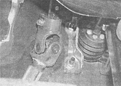
12. Remove the upper left and lower right nuts securing the pedal bracket to the servo unit.

A — Left brake booster mounting nuts

B — Right brake booster mounting nuts

A.
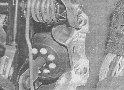
B — Right brake booster mounting nuts


B.
B — Right brake booster mounting nuts


13. Remove the servo from the engine compartment bulkhead, being careful not to damage the brake pipes or other nearby components. Remove the sealing gasket.


Models without air conditioning


Models with ABS


1. Remove the hydraulic modulator assembly (see Removal and installation of ABS and TCS components).

2. Remove the brake master cylinder (see Removal and installation the master brake cylinder).

3. Unscrew the hydraulic modulator bracket mounting bolts.

4. Disconnect the vacuum tube from the booster or remove the check valve.

5. Remove the driver's footwell side trim panels and disconnect the foot brake pedal return spring.

6. Remove the retainer and separate the brake booster servo push rod from the foot brake pedal. Remove the washer.

Material copied from the portal: www.OPELBOOK.ru

7. Remove the upper left and lower right nuts securing the pedal bracket to the servo unit.

8. Remove the servo from the engine compartment bulkhead, being careful not to damage the brake lines or other nearby components. Remove the sealing gasket.

Models without ABS


1. Remove the brake master cylinder (see Removal and installation the master brake cylinder).

2. Disconnect the vacuum tube from the booster or remove the check valve.

3. Separate the relay stand from the support bracket and move it to the side, remove the multi-pin connector from the bracket.

4. Loosen the nuts of the union nut connections of the brake pipes laid between the master cylinder and the adapter nozzle.

5. Place a rag under the adapter and turn it inside out.

6. Remove the driver's footwell side trim panels and disconnect the foot brake pedal return spring.

7. Remove the retainer and separate the brake booster servo push rod from the foot brake pedal. Remove the washer.


8. Remove the upper left and lower right nuts securing the pedal bracket to the servo unit.

9. Remove the servo from the engine compartment bulkhead, being careful not to damage the brake lines or other nearby components. Remove the sealing gasket.

Installation


Installation is carried out in the reverse order of dismantling the components.

1. Be sure to replace the sealing gasket installed between the servo assembly and the engine compartment bulkhead. Make sure all fasteners are tightened to the required torque.

2. Finally, bleed the brake system (see Bleeding the brake system), then start the engine and check the vacuum line connections for leaks.


This article is available at russian, bulgarian, belarusian, ukrainian, serbian, croatian, romanian, polish, slovak, hungarian
Checking the article: Pavlovsky Nikolay

Share information:

Previous articles
Opel Astra G: Brake system
Next articles

Removal and installation the foot brake pedal
Removal and installation the master brake cylinder
Removal, maintenance and installation of wheel cylinders of drum brake mechanisms of rear wheels
Removal, repair and installation of rear wheel disc brake calipers
Removal, repair and installation of front wheel disc brake calipers
Removal, inspection and installation of the brake drum
Removal, checking the correct operation and installation of the brake booster check valve
Removal and installation the brake booster servo vacuum pump (diesel models)
Checking the proper functioning of the brake booster servo vacuum pump (diesel models)
Adjusting the parking brake drive
Removal and installation the parking brake lever
Removal and installation parking brake cables


See similar ones from other Opel car manuals:
▶ Checking the proper functioning and tightness of the brake… Opel Corsa B (1993-2000)
▶ Checking, removing and installing the brake booster assembly Opel Vectra C (2002-2008)
▶ Front Brake Pads — Checking, Removing and Installing Opel Omega B2 (1999-2003)
▶ Checking the vacuum in the brake booster system Opel Insignia A (2008-2017)
▶ Checking, removing and installing injection valves… Opel Kadett D (1979-1984)
Link to this page in different formats

Visitor comments


No comments yet


How much will 11 + 32 =


Astra J (2009-2015, petrol) 
  • General information
  • Vehicle device
  • User manual
  • Faults en route
  • Maintenance
  • Power unit
  • Engine repair
  • Cooling and lubrication system
  • Engine power system
  • Exhaust system
  • Transmission
  • Clutch
  • Car gearbox
  • Drive shafts
  • Chassis
  • Front suspension
  • Rear suspension
  • Steering
  • Brake system
  • Wheels and tires
  • Body
  • Exterior
  • Interior
  • Doors and windows
  • Body Care
  • Heating and air conditioning
  • Security systems
  • Electrical equipment
  • Equipment and devices
  • Lighting and signaling
  • Power devices
  • Electrical circuits
Astra H (2004-2009) 
  • General information
  • Introduction to the guide
  • Troubleshooting
  • User manual
  • Maintenance
  • Power unit
  • Engine repair
  • Cooling and heating
  • Power and exhaust system
  • Ignition system
  • Launch and charge system
  • Transmission
  • Mechanical gearbox
  • Automatic gearbox
  • Drive shafts
  • Chassis
  • Brake system
  • Car suspension
  • Steering
  • Body
  • Interior
  • Exterior
  • Electrical equipment
  • Equipment and devices
  • Electrical circuits
Astra G (1998-2004) 
  • General information
  • Introduction to manual
  • User manual
  • Maintenance
  • Power unit
  • SOHC gasoline engines
  • DOHC gasoline engines
  • Diesel engines 1.7 and 2.0
  • Engine repair
  • Cooling system
  • Supply system
  • Injection system (gasoline)
  • Injection system (diesel)
  • Exhaust system
  • Charge and launch system
  • Ignition system (gasoline)
  • Preheat system (diesel)
  • Transmission
  • Manual gearbox
  • Automatic gearbox
  • Clutch
  • Drive shafts
  • Chassis
  • Brake system
  • Wheel suspension
  • Steering
  • Body
  • Exterior
  • Interior
  • Doors and windows
  • Ventilation and heating
  • Electrical equipment
  • Equipment and devices
  • Electrical circuits
Astra G (1998-2004, petrol) 
  • General information
  • User manual
  • Car care
  • Maintenance
  • Power unit
  • Single shaft engines
  • Twin shaft engines
  • Engine repair
  • Cooling and heating
  • Fuel and exhaust systems
  • Starting and charging system
  • Ignition system
  • Transmission
  • Clutch
  • Mechanical gearbox
  • Automatic gearbox
  • Drive shafts
  • Chassis
  • Brake system
  • Car suspension
  • Steering
  • Body
  • Interior
  • Exterior
  • Electrical equipment
  • Equipment and devices
  • Wiring diagrams Opel Astra
  • Wiring diagrams Opel Zafira
Astra F (1991-1998, petrol) 
  • General information
  • Maintenance
  • Power unit
  • Engine in car
  • Engine removed
  • Cooling system
  • Heating and ventilation
  • Fuel supply (carburetor)
  • Fuel supply (injector)
  • Emission control
  • Ignition system
  • Transmission
  • Clutch
  • Mechanical gearbox
  • Automatic gearbox
  • Drive shafts
  • Chassis
  • Brake system
  • Car suspension
  • Steering
  • Body
  • Exterior
  • Interior
  • Electrical equipment
  • Equipment and devices
  • Electrical circuits
OpelBook.ru © 2017–2026 · Mobile version · · Sitemap: EN BG BY UA RS HR RO PL SK HU · Feedback · Site search
Astra F, petrol · Astra G, petrol · Astra G · Astra H · Astra J, petrol · Corsa B · Corsa C, petrol · Corsa C · Insignia A · Kadett D · Kadett E · Omega A · Omega B · Omega B2 · Vectra A, petrol · Vectra A · Vectra B, petrol · Vectra B · Vectra C · Zafira A, petrol · Frontera A, petrol · Frontera B · Ascona C · Vivaro A ·
We want your visit to be comfortable 🤝! We use cookies 🍪 to make that happen.