
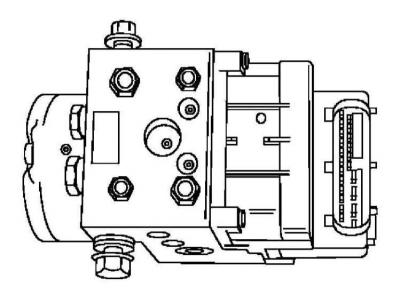
Hydraulic modulator and electronic control unit (ECU)
Removing
1. Remove the battery (see chapter Engine electrical equipment).
2. Disconnect the two multi-pin connectors from the relay mounting bracket.
3. Remove the cover of the mounting block, release the latter from the support bracket and move it aside.
4. Release from an arm plaits of electroconducting.
5. Loosen the three fixing nuts and remove the relay mounting block support bracket.
6. Remove the holder from the brake pipes.
7. Remove the GTZ reservoir cap and pump out all of its liquid with a syringe or rubber bulb.
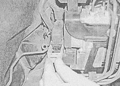
8. Mark the brake pipes, loosen the nuts of the nipple connectors and disconnect the pipes from the modulator - in order to prevent rounding of the slots of tightly tightened nuts, use a spanner wrench with a split head. Get ready to collect the spilled liquid - place a rag under the fitting connectors. Also disconnect the brake lines from the GTZ (see Removal and installation of the main brake cylinder). Seal or tape the openings in the modulator, cylinder, and pipes immediately to prevent dirt from entering the system.
9. After releasing the latch, disconnect the special multi-pin connector at the top of the hydraulic modulator.
10. Give the fixing bolts / nuts, remove the modulator and the ABS control unit from the support bracket and remove them from the engine compartment - try not to let the brake fluid get on the painted body surfaces.
To minimize fluid loss, do not turn the modulator upside down during disassembly.
Installation
Installation is carried out in the reverse order to the dismantling of the components.
Finally, bleed the brake system (see Bleeding the brake system).
Wheel sensors
Replacement
The sensors are built into the wheel hubs and, in case of failure, must be replaced with them (see chapter Suspension and steering).
TCS switch
Removing
1. Carefully prying off with a screwdriver, remove the sensor from the instrument panel, - in order to avoid damage to the panel, place a piece of cardboard or rags under the screwdriver.
Installation
Installation is carried out in the reverse order to the dismantling of the components.
ABS control unit
Removing
1. Remove the hydraulic modulator from the assembly of the electronic control unit (ECU) ABS (see above).
2. Disconnect the electrical wiring, unscrew the mounting bolts and remove the ABS ECU from the hydraulic modulator, - try not to damage the coil holder.
3. Remove the sealing element installed between the coil holder and the control unit.
Installation
1. Lay a new sealing element, install the ECU on the hydraulic modulator assembly and, in several stages, tighten the new mounting bolts to the required torque (see Specifications), - do not deform the ECU when installing it on the modulator. If the bolts are tight, the block must be replaced as an assembly.
If a spring plate was installed between the hydraulic modulator and the control unit during removal, it should not be reinstalled.
2. Further installation is carried out in the reverse order to the dismantling of the components.
Visitor comments