
Warning! Before performing the operation, be sure to read the section «Safety measures for the maintenance and repair of the engine management system».
You will need a multimeter to do the job.
Execution sequence
1. We prepare the car for work (see «Preparing the car for maintenance and repair»).
2. Relieve pressure in the fuel line (see «Fuel Line - Pressure Relief»).
3. Remove the decorative trim of the engine (see «Decorative overlay of the engine - removal and installation»),
4. On 1.4 and 1.6 DOHC engines, remove the coolant supply hose to the throttle assembly from the holders on the cylinder head cover and set it aside (see «Cylinder head cover for 1.4 and 1.6 DOHC engines - removal, gasket replacement and installation»).
5. Disconnect the hoses of the crankcase ventilation system from the cylinder head cover (see «Cylinder head cover for 1.4 and 1.6 DOHC engines - removal, gasket replacement and installation» or «1.8 DOHC engine cylinder head cover - removal, gasket replacement and installation»),
6. On engines 1.4 and 1.6 DOHC, remove the air inlet (see «Throttle assembly - removal, gasket replacement and installation»).
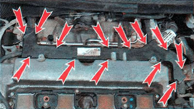
7. Using a slotted screwdriver, we alternately disengage 12 holders on engines 1.4 and 1.6 DOHC...
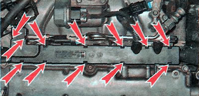
... or 13 holders on the 1.8 DOHC engine and remove the top cover of the protective cover of the wiring harness.
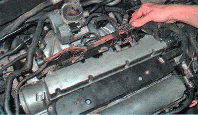
8. Remove the wiring harness from the protective cover (shown on the example of a 1.6 DOHC engine, on other engines the harness is removed in the same way).
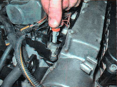
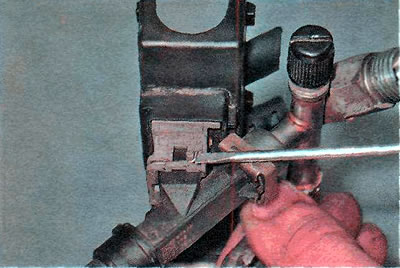
9. With a slotted screwdriver, slightly bend the latch...
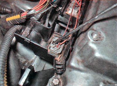
... and disconnect the wiring harness block from the nozzle of the first cylinder (shown on 1.6 DOHC engine, similar on other engines).
10. Similarly, disconnect the pads from the injectors of the remaining cylinders and take the wiring harness to the side.
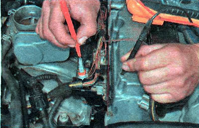
11. Alternately connect the multimeter in voltmeter mode to terminals 1 of the injector wiring harness blocks and to «mass» car (shown on 1.6 DOHC engine, similar on other engines). We turn on the ignition and take readings of the device. The voltage must be at least 12 V. Turn off the ignition.
In the absence of voltage, check the fuse Ef6 (see «Fuse and relay mounting blocks»). If the fuse is blown, replace it. Turn on the ignition again. If the fuse blows again, then there is a short circuit in the circuit that needs to be repaired (see «Checking and repairing electrical circuits»).
12. If the fuse is intact, check relay E4 (see «Fuse and relay mounting blocks», «Relay test»),
13. If the fuse and relay are intact, but there is no voltage, then there is an open circuit in the circuit that must be eliminated (see «Checking and repairing electrical circuits»).
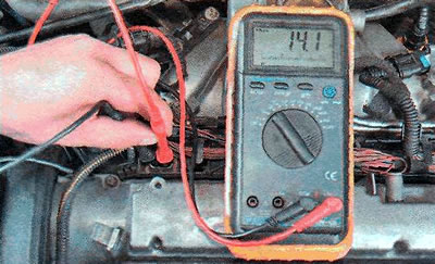
14. With a multimeter in ohmmeter mode, we check the resistance of the nozzle winding, for which we connect the multimeter leads to the nozzle contacts. The resistance should be around 13-14 ohms, otherwise the injector needs to be replaced. Check the rest of the injectors in the same way (shown on 1.6 DOHC engine, similar on other engines).
15. With the help of two wires directly from the battery, we briefly apply a voltage of 12 V to the injector contacts. A serviceable injector should have a characteristic click when the valve is opened. Replace defective injectors.
Comment. Subsequent operations are only necessary to remove the fuel rail and to replace the injectors.
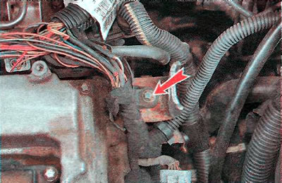
16. On 1.4 and 1.6 DOHC engines, disconnect the knock sensor wiring harness block...
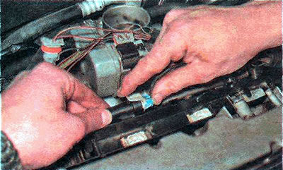
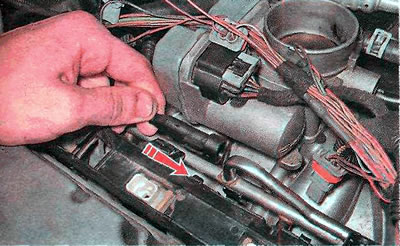
... and disconnect the wiring harness block from the protective cover by sliding it in the direction indicated by the arrow.
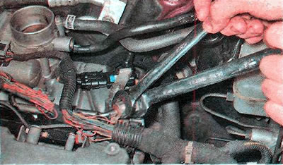
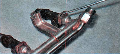
17. Holding the fuel rail fitting with a 17 mm wrench, unscrew the pipeline nut with a 19 mm wrench and disconnect it from the fuel rail (shown on 1.6 DOHC engine, similar on other engines).
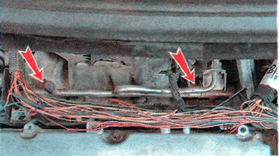
18. On engines 1.4 and 1.6 DOHC, use the TORX E8 key to turn the right...
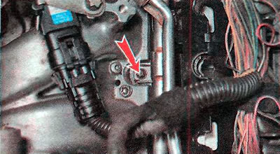
...and the left fuel rail mounting bolts.
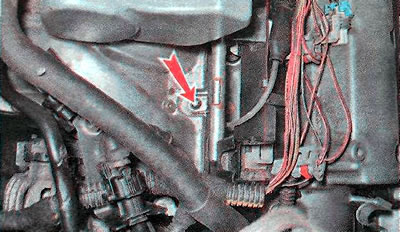
19. On the 1.8 DOHC engine, use the TORX E10 key to unscrew the bolt securing the protective cover...
... and with a TORX E8 key - two fuel rail mounting bolts.
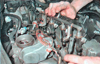
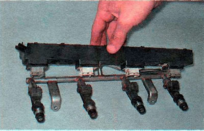
20. Pulling up, remove the fuel rail assembly with injectors and the lower part of the protective cover (shown on 1.6 DOHC engine, similar on other engines).
Warning! Replace the lower injector O-rings each time the fuel rail assembly with injectors is removed (see below).
Comment. Further execution of the operation is shown on the 1.6 DOHC engine, similarly on other engines.
21. Using a slotted screwdriver, pry off and remove the nozzle block retainer.
22. In a similar way, remove all other latches and disconnect the protective cover.
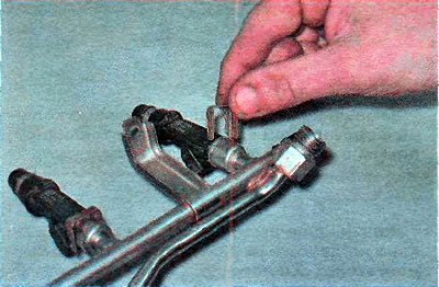
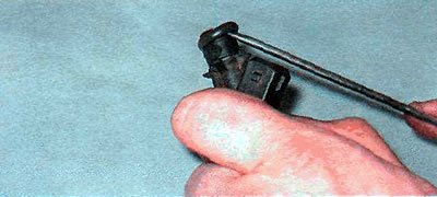
23. Using a slotted screwdriver, pry off the nozzle retainer...
...and take it off.
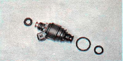
24. Remove the nozzle from the fuel rail.
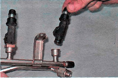
Warning! Replace the upper O-rings of the injectors when removing the injector from the rail.
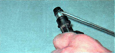
25. Pry off the top sealing ring of the injector with a screwdriver and remove it.
26. Similarly, remove the lower sealing ring.
Comment. The 1.8 DOHC engine has three o-rings.
27. Install all removed parts in reverse order. When installing new injector O-rings, make sure that they do not twist.
Recommendation. To facilitate the installation of the injector into the fuel rail, as well as to install the fuel rail into the intake manifold, lubricate the injector o-rings with a thin layer of technical vaseline or gear oil.
Visitor comments