


Warning! Do not open the expansion tank cap or remove the thermostat until the engine has cooled down completely! See also Section 2.
General information
1. The thermostat is designed to speed up the engine warm-up process and divides the cooling system into two circuits: large and small. Until the coolant temperature reaches a certain value (as a rule, thermostats are adjusted to a temperature 80-90°C) the thermostat valve is closed and the liquid circulates along the small circuit without getting into the radiator. As a result, the engine quickly warms up to normal operating temperature. When a certain threshold value of the coolant temperature is exceeded, the thermostat filler begins to expand and opens the valve - the liquid begins to circulate along the large circuit through the radiator.
2. The thermostat housing is attached to the engine. The location of the thermostat may vary depending on the layout of the power unit, but it is easy to find - it is always connected to the upper radiator hose.
3. Below is a detailed description of the procedure for removing/installing the thermostat on Z16XE/Z18XE engines; for other engines, we will only provide the differences and features.
Removal/installation
Engines Z16XE/Z18XE
4. Drain the coolant (see Section 3).
Note: It is not necessary to drain the coolant completely. It is enough for the coolant level to drop below the thermostat housing.
5. Remove the engine cover (see Chapter 2) and, having loosened the fastening clamp, disconnect the upper hose of the cooling system from the thermostat housing.
6. Disconnect the hose (see accompanying illustration) cooling system, disconnect the coolant temperature sensor wiring connector, unscrew the 2 mounting bolts (on the Z16XE engine - 3 bolts) and remove the thermostat housing from the engine.
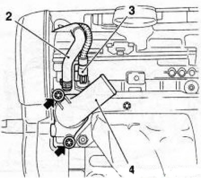
9.6 Thermostat housing (4) (using the Z18XE engine as an example) - the arrows indicate the mounting bolts: 2. Cooling system hose; 3. Coolant temperature sensor wiring connector
7. Check the thermostat (see below if necessary thermostat together with the housing. When replacing, do not forget to reinstall the coolant temperature sensor into the housing of the new thermostat, tighten it with the required force (see Specifications).
8. Installation is performed in the reverse order of removal. Replace the sealing gasket before installation (see accompanying illustration) thermostat and tighten the thermostat housing mounting bolts to the required torque.
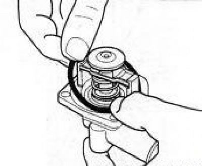
9.8 Replace the thermostat sealing gasket before installation
9. Fill the system with coolant (see Section 3).
10. Start the engine, warm it up to operating temperature and check for leaks.
Features of the Z19DT engine
11. Remove the cooler (see accompanying illustration) exhaust gas recirculation systems.
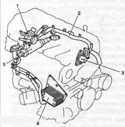
9.11 Elements of the cooling system of Z19DT(H) engines: 1. Thermostat housing; 2. Cooling system pipe; 3. Water pump; 4. Heat exchanger; 5. Exhaust gas recirculation system cooler
12. Disconnect the 3 cooling system hoses from the thermostat housing.
Features of the Z19DTH engine
14. Remove the battery (see Chapter 5).
15. Remove the preheater control unit and carefully move it to the side.
16. Unbolt the cooling system pipe and disconnect 4 hoses from the thermostat housing.
Features of Y20DTH/Y22DTR engines
17. Remove the turbocharger hose (see illustration 7.27).
18. Disconnect the preheating hose from the turbocharger to the regeneration system valve and move it to the side.
19. Unscrew the 4 mounting bolts and remove the housing (see accompanying illustration) thermostat, and, if necessary, a coolant temperature sensor.
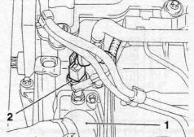
9.19 Thermostat housing (1) and coolant temperature sensor (2) (y20DTH/Y22DTR engines)
Features of the Z20NET engine
20. When draining the coolant, unscrew the drain plug located at the bottom of the water pump (see accompanying illustration).
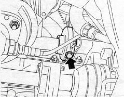
9.20 Drain plug (indicated by the arrow) water pump (z20NET engine)
21. Remove the air cleaner (see Chapter 4) and remove the vacuum pump.
22. Remove 3 bolts (see accompanying illustration) fasteners and remove the thermostat housing.
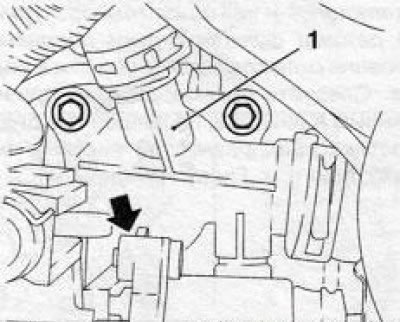
9.22 Thermostat housing (1) mounting bolts (z20NET engine) the arrow indicates the position of the third bolt
23. Installation is carried out in the reverse order of removal. Do not forget to replace the vacuum pump sealing gasket, before screwing in the water pump drain plug, wrap its thread with Teflon tape or lubricate it with sealing sealant.
Features of Z22SE/ Z22YH engines
24. When draining the coolant, unscrew the drain plug located at the bottom of the water pump (see illustration 9.20).
25. Loosen the clamp (see accompanying illustration) fasteners and disconnect the hose from the thermostat housing. Unscrew the 2 mounting bolts and remove the thermostat housing from the engine.
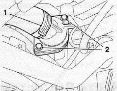
9.25 Bolts (2) for fastening the thermostat housing and fastening clamp (1) for the cooling system hose (engines Z22SE/Z22YH)
26. Installation is performed in the reverse order of removal. Do not forget to replace the thermostat sealing gasket, lightly lubricating it with silicone grease (white color). Before screwing in the water pump drain plug, wrap its threads with Teflon tape or lubricate it with sealing sealant
Examination
27. The main reason for thermostat failure is the aging of the filler and its loss of ability to significantly change its volume depending on the temperature. Mechanical damage to the thermostat valve may also occur during operation.
28. You can check the thermostat's functionality beforehand without removing it from the engine. With the engine running, open the hood and touch the upper radiator hose.
Warning! Be careful - at high coolant temperature you can burn your hand!
If the engine has just started and has not yet reached operating temperature, and the liquid in the upper hose is already warm, then the thermostat valve is not closed. This is also indicated by a slower than usual increase in the coolant temperature, and in winter - a decrease in the heater power. If the control lamp has been activated (see Chapter "Controls and operating techniques", Section 16) coolant temperature on the instrument panel, and the upper pipe is cold - it is guaranteed to say that the valve does not open the large circuit.
Note: This is only a rough check, and you must be sure that all other components of the cooling system and temperature control are functioning properly and that the coolant level is normal.
Follow the recommendations in the section on diagnosing cooling system problems.
29. The most accurate results are obtained by checking the thermostat on a workbench.
30. Remove the thermostat from the engine (see above).
31. Attach a piece of wire to the thermostat assembly and lower it into a container filled with water (see accompanying illustration). Put the thermometer there too.
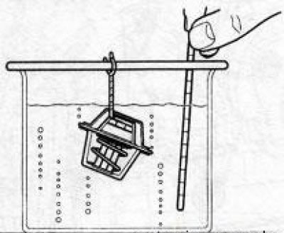
9.31 Checking the proper functioning of the thermostat
Attention! Make sure that the thermometer and thermostat do not come into contact with the walls and bottom of the container
32. Begin to slowly heat the water, monitoring the change in the thermometer readings. The thermostat valve should operate in strict accordance with the control settings for a specific engine model (see Specifications).
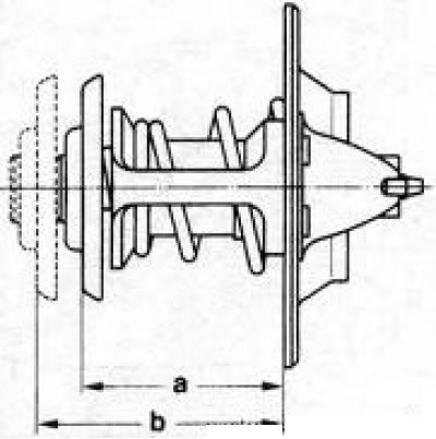
9.33 Checking the complete opening of the thermostat valve
33. Estimate the value of the full opening of the valve, - the nominal value is b-a=8 mm (see accompanying illustration). If any deviations are detected, replace the thermostat.
Visitor comments