
2. The cooling system can operate in one of three modes. At the first stage, when the engine is started, until the temperature of the coolant has risen above a certain value, the coolant circulates in a small circle, from which the radiator is excluded. As the liquid warms up, the valve of the thermostat included in the system path opens and the radiator is included in the circulation circuit. The liquid passes through the radiator from top to bottom and is cooled as a result of blowing the radiator fins with outside air. When the car is constantly moving at forward and high speeds, as a rule, the flow of oncoming air is sufficient for normal cooling of the liquid. With a certain increase in engine speed, as well as when the temperature of the coolant reaches the next control value, the adjustable electric fan of the cooling system is activated, which pumps additional air flow, which significantly increases the efficiency of the radiator heat exchanger. The moment of turning on the fan and the number of its revolutions are determined by the engine control device (ECM) using data received from the coolant temperature sensor. The fan is switched on through one or more relays. Depending on the type of engine and configuration, 1 or 2 fans can be installed on the car.
3. The cooling system is hermetically sealed and tightly sealed with a expansion tank cap that can withstand a certain overpressure (1.2-1.5 bar), which ensures an increase in the boiling point of the coolant and, accordingly, the efficiency of heat removal through the radiator. A decrease in the boiling point can lead to the formation of stagnation zones, which reduces the cooling efficiency of the engine. For this reason, the cooling system must be filled with an appropriately formulated coolant all year round. If the internal pressure in the system exceeds a certain value, the excess coolant flows through the connecting hose into the expansion tank. As the system cools down, the fluid automatically returns from the reservoir to the radiator.
4. Adding coolant to the system is done through the neck of the expansion tank (see chapter 1), which at the same time also acts as a receiver, accumulating the excess liquid displaced from the radiator.
5. In view of the above design features, such a cooling system was called closed, since it excludes any functional loss of the working fluid.
Heating and ventilation system
6. The main components of the interior heating system (see resist. illustrations) are an electric fan with several speeds and a heat exchanger placed in a box-shaped heater casing, fixed under the dashboard of the car. The heat exchanger is connected to the engine cooling system by means of hoses. The control unit for the functioning of the heater / air conditioner is mounted in the instrument panel of the car. The coolant heated in the engine circulates through the heater heat exchanger, giving off its heat to the air filling the casing. When the interior heating is turned on, the leaf damper opens, as a result of which the internal volume of the heater casing is connected to the volume of the passenger compartment. When the fan is turned on, the impeller of the latter begins to drive the air supplied to the passenger compartment through the heat exchanger, providing it with intensive heating. Air exits the passenger compartment through vents at the rear of the vehicle.
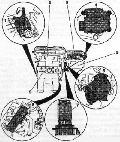
1.6a Main elements of the HVAC system: 1. Mixing damper drive electric motor; 2. Air distributor housing; 3. Damper body of air circulation system; 4. Electromotor drive of the circulation damper (only when installing air conditioning); 5. Fan electric motor; 6. Electric motor drive control air flow distribution; 7. Resistive assembly and fan motor; 8. Heat exchanger
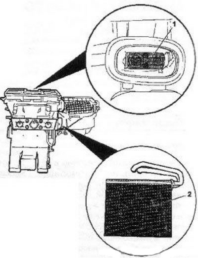
1.6b HVAC system elements: 1. Upper duct temperature sensor (only when installing an electronically controlled air conditioner); 2. Evaporator; 9. Control panel for heater/air conditioner operation (HVAC)
7. Air is supplied to the cabin through the front level deflectors, footwell nozzles and windshield air deflectors (see illustration 1.7a). Before air enters the passenger compartment, it is cleaned by a dust filter. A schematic diagram of the distribution of the air flow is shown in illustration 1.7b.
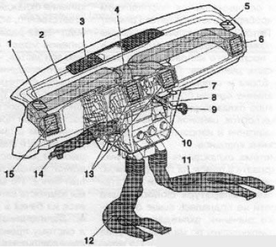
1.7a Sleeves for supplying air to the passenger compartment: 1, 5. Upper side deflectors for blowing side windows; 2. Sleeve air supply to the windshield; 3. Deflectors blowing the windshield; 4. Sleeves of air supply to the front level; 6, 15. Side deflectors of the front level; 7. Fan electric motor; 8. Air supply hose to the main glove box (with appropriate equipment); 9. Main glove box air valve (with appropriate equipment); 10. Air supply hose to the passenger foot well; 11, 12. Right / left sleeves for air supply to the rear leg wells; 13. Central deflectors of the front level; 14. Air supply hose to the driver's footwell
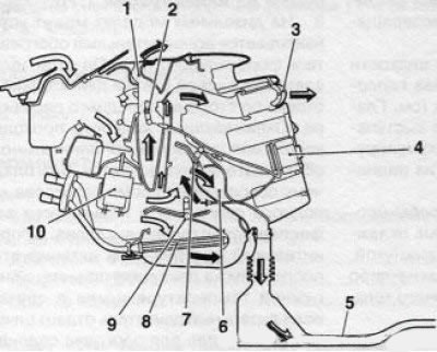
1.7b Schematic diagram of air distribution: 1. On the windshield; 2. Distribution damper; 3. On the front level; 4. Control panel; 5. Into the rear foot wells; 6. In foot wells; 7. Distribution damper; 8. Heat exchanger; 9. Mixing damper; 10. Heater fan drive electric motor
8. On diesel models, an additional heater of the injector type can be installed. It is installed on the rear wall of the engine compartment on the front passenger side. The coolant passes through the auxiliary heater heat exchanger and is heated, thereby reducing the warm-up time of a cold engine and increasing the efficiency of interior heating. The auxiliary heater is activated when the engine is started at low outside temperatures and/or if the diesel engine produces too little heat to heat the passenger compartment.
9. Messages about the occurrence of malfunctions in HVAC systems are recorded in the electronic memory unit of the ECM and can be read when a special scanner is connected - accurate diagnosis is not possible without the above device.
10. The rules for using the controls for the operation of HVAC systems are detailed in Chapter «Controls and methods of operation».
Attention! If, as part of work on the heater, work is also carried out on the electrical system, the battery must be disconnected (see chapter 5).
Air conditioning system (K/V)
11. At the request of the owner, the car can be equipped with air conditioning. The air conditioner is installed as a single system with the heating system, together with it, maintains the set air temperature in the cabin.
12. The air conditioning system includes a condenser mounted on the radiator of the cooling system, an evaporator located next to the heat exchanger of the heater, a compressor mounted on the engine block, and a receiver-drier (battery), equipped with a high pressure reducing valve. All components are interconnected by refrigeration lines (see resist. illustration). The compressor is driven from the crankshaft by means of a multiribbed belt.
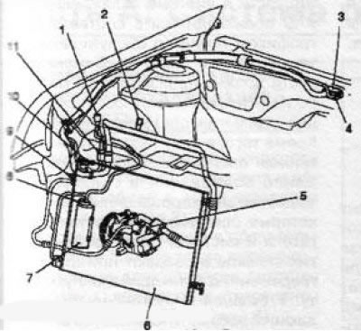
1.12 The general layout of the elements of the A/C system in the engine compartment: 1. Service connector of the high-pressure circuit; 2. Service connector of the low-pressure circuit; 3. Expansion valve; 4. Connecting connector; 5. Compressor; 6. Capacitor; 7. Receiver dryer; 8. Connecting connector; 9. Service connector of the high-pressure circuit; 10. Pressure sensor of the K / V system; 11. Separator of the refrigeration line
13. The principle of operation of the air conditioning system is schematically shown on resist. illustrations. In cooling mode, the air conditioner works like a refrigerator: the compressor compresses the refrigerant gas (R 134 freon free), while the refrigerant is heated and sent to the condenser, where it cools and compresses. Passing through the expansion valve, the refrigerant expands and enters the evaporator, turning into steam, the process is accompanied by a strong absorption of heat.
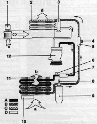
1.13 Functional diagram of the K / V% system: 1. Fan; 2. Evaporator; 3. Expansion valve; 4. Service connector of the low-pressure circuit; 5. Pulsation damper; 6. Service connector of the high-pressure circuit; 7. Pulsation damper; 8. Pressure switch; 9. Receiver-drier; 10. Additional fan; 11. Capacitor; 12. Compressor; A. The inlet flow of cold air driven through the condenser heat exchanger; b. The output stream of heated air, driven through the condenser heat exchanger and taking heat from the refrigerant; With. Air flow generated by the fan; d. The air flow driven through the evaporator heat exchanger; A. The gas phase of the high-pressure circuit; B. The liquid phase of the high-pressure circuit; C. The liquid phase of the low-pressure circuit; D. Low pressure gas phase
14. The fan drives the air entering the passenger compartment through the evaporator heat exchanger. Due to the process of evaporation and expansion of the refrigerant, the heat of the air flowing around the evaporator is absorbed. The air is cooled and the resulting moisture turns into condensate, which is directed outside the vehicle interior. The intensity of the cooling process depends on the set temperature and on the setting of the fan switch.
15. At the request of the user, the air conditioning system can be turned off, which turns off the compressor, and for vehicles with a diesel engine, in addition, the additional heating element is turned off - this significantly reduces fuel consumption.
16. HVAC system with automatic temperature control can be installed as an option (climate control). The automatic operation mode maintains a constant, user-selected temperature in the passenger compartment and dehumidifies the air entering the passenger compartment. In addition, the amount and distribution of air supplied to the passenger compartment are automatically regulated, as well as fluctuations in outside temperature are compensated. When ECO mode is activated (ECO) the air conditioner is turned off, but the heating and ventilation systems continue to operate in automatic mode.
17. The rules for using the controls for the operation of heating, ventilation and air conditioning systems are detailed in Chapter «Controls and methods of operation».
18. The lubrication of the moving parts of the A/C system is ensured by the components contained in the refrigerant and its regular circulation, which prevents the formation of pores in the seals and the occurrence of corrosion. Therefore, even if there is no need to use the air conditioner, especially during the cold season, it should be turned on at least once a month for a short time at the highest power. Switching on should be carried out at a uniform speed of the vehicle and with a warm engine.
Attention! Work on the air conditioner must only be carried out by service stations. For this reason, repair of the air conditioner is not described here! Do not open the refrigerant circuit, as the refrigerant may cause frostbite if it comes into contact with the skin!
Security measures for servicing the A/C system
The A/C system should only be serviced by trained technicians who are trained in safe work practices using the proper equipment and in compliance with depressurization rules, as well as familiar with the methods of collecting and storing automotive refrigerant.
- Avoid skin contact with refrigerant;
- When working near the A/C system, wear protective goggles;
- If refrigerant comes into contact with skin or eyes, do not rub the affected area. Immediately flush the affected area with cold water for at least 15 minutes. Seek immediate medical attention at a healthcare facility. Self-medication is not allowed;
- The refrigerant is stored in pressurized cylinders. Store the cylinder at a temperature not exceeding +50°. Take measures to prevent the cylinder from falling from a height or other situations that may lead to its damage;
- Work should be carried out in a well-ventilated area. The refrigerant is colorless and odorless, evaporates quickly, leads to a decrease in oxygen access and difficulty breathing;
- The gaseous refrigerant is heavier than air and must collect relatively quickly at the bottom, for example, under a car;
- When the refrigerant burns, poisonous gas is produced. Keep refrigerant away from open flames. Do not smoke when working with the A/C system;
- When carrying out welding work near the A/C system, do not expose it to high temperatures or open flames. Overheating can lead to an increase in pressure in the system and ignition;
- Cleaning the condenser or evaporator with steam is not permitted. Use only cold water or compressed air.
Visitor comments