
OpelBook.ru
Cars AvtoVAZ Cars Mitsubishi Cars BMW Cars Mercedes Cars Nissan Cars Toyota Cars Chevrolet
English Русский
Български
Беларускі
Український
Српски
Hrvatski
Română
Polski
Slovenský
Magyar
 |  Sitemap  |  Contacts  |    


Main Astra Corsa Insignia Kadett Omega Vectra Zafira Others Articles
Corsa B (1993-2000) Corsa C (2000-2006, petrol) Corsa C (2000-2006)
  • Main
  • Corsa
  • Corsa C
  • Power unit
  • Cooling system
  • Engine cooling system — design description

Engine cooling system — design description (Opel Corsa C)

            0

1. All models of the vehicles considered in this Manual are equipped with a positive pressure engine cooling system with thermostatic control of the working fluid circulation. The fluid circulation is provided by a water pump, which is permanently operating during engine operation and is fixed to the engine block. The pump is driven, depending on the engine model, by a multi-rib or toothed belt/chain. The fluid flow washes the areas of each cylinder in the block, after which it is directed to the rear of the engine. Cooling channels laid in the block and cylinder head casting provide intensive cooling of the intake and exhaust ports, spark plug installation areas and exhaust valve guides.

2. The cooling system can operate in one of three modes. In the first stage, when the engine is started, until the coolant temperature rises above a certain value, the coolant circulates in a small circuit, from which the radiator is excluded. As the liquid warms up, the valve of the thermostat included in the system tract opens and the radiator is included in the circulation circuit. The liquid passes through the radiator from top to bottom and is cooled as a result of outside air blowing on the radiator fins. When the car is constantly moving at medium and high speeds, as a rule, the oncoming air flow is sufficient for normal cooling of the liquid. With a certain increase in engine speed, as well as when the coolant temperature reaches the next control value, the adjustable electric fan of the cooling system is activated, the additional air flow pumped by it significantly increases the efficiency of the radiator heat exchanger. The moment of switching on the fan and the number of its revolutions are determined by the engine control unit (ECM) using data received from the coolant temperature sensor. The fan is switched on through one or more relays.


3. Depending on the engine type and configuration, the vehicle may be equipped with 1 or 2 fans. On models produced from September 2000 to August 2003 with petrol engines and the A/C system, an additional fan was installed in addition to the main one; on models of later release, one more powerful fan was installed.

Note: The power of the main fan has been increased from 187 to 350 W. On diesel models, a so-called cooling module is installed (see accompanying illustration), which consists of a radiator and two fans located in front and behind the radiator. If equipped appropriately, a condenser of the air conditioning system can also be installed between the fans.
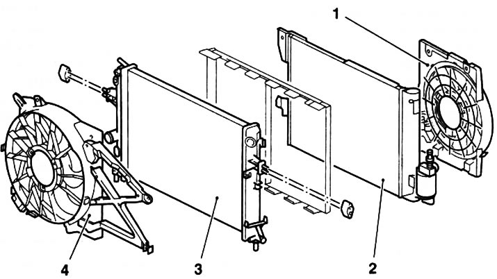

1.3. Cooling module: 1. Assembling the front radiator (only diesel models with C/V); 2. Capacitor…

1.3. Cooling module: 1. Assembling the front radiator (only diesel models with C/V); 2. Capacitor K/V; 3. Radiator; 4. Assembling the rear radiator


4. The cooling system has a sealed design and is tightly closed with an expansion tank cap capable of withstanding a certain excess pressure (1.2-1.5 bar), which increases the boiling point of the coolant and, accordingly, the efficiency of heat removal through the radiator. A decrease in the boiling point can lead to the formation of stagnation zones, which reduces the efficiency of engine cooling. For this reason, the cooling system must be filled with a coolant of the appropriate composition all year round (see Specifications). When the internal pressure in the system exceeds a certain value, the excess coolant flows through the connecting hose into the expansion tank. As the system cools down, the liquid automatically returns from the tank to the radiator.


5. Add coolant to the system through the neck of the expansion tank (see Chapter 1).

6. Due to the listed design features, such a cooling system is called closed, since any functional losses of the working fluid are excluded.

Original article on the web portal (OpelBook.ru)


This article is available at russian, bulgarian, belarusian, ukrainian, serbian, croatian, romanian, polish, slovak, hungarian
Checking the article: Kornev Georgy

Share information:

Previous articles
Opel Corsa C: Cooling system
Next articles

Cooling and Heating System Specifications
Antifreeze — General Information and Precautions
Draining and filling the system with coolant
Disconnecting and replacing cooling system hoses
Cooling system maintenance, flushing and leak testing
Removal and installation the cooling system fan
Removal and installation the cooling system radiator


See similar ones from other Opel car manuals:
▶ Description of the design of the engine cooling system Opel Vectra C (2002-2008)
▶ Engine cooling system Opel Astra H (2004-2009)
▶ Filling the cooling system — 2.8L petrol engine Opel Insignia A (2008-2017)
▶ Carburetor engine cooling system Opel Kadett E (1984-1995)
▶ Identifying and troubleshooting engine cooling system faults Opel Omega B2 (1999-2003)
Link to this page in different formats

Visitor comments


No comments yet


How much will 38 + 27 =


Corsa C (2000-2006) 
  • General information
  • Introduction to guide
  • Troubleshooting
  • Vehicle device
  • User manual
  • Maintenance
  • Power unit
  • Engine repair
  • Cooling system
  • Power and exhaust system
  • Control system
  • Engine electrical equipment
  • Transmission
  • Clutch
  • Mechanical gearbox
  • Automatic gearbox
  • Drive shafts
  • Chassis
  • Brake system
  • Wheel suspension
  • Steering
  • Body
  • Exterior
  • Interior
  • Doors and windows
  • Heating and air conditioning
  • Electrical equipment
  • Equipment and devices
  • Lamps and lighting
  • Electrical circuits
Corsa C (2000-2006, petrol) 
  • User manual
  • Car access
  • Governing bodies
  • Seat control
  • Heating and air conditioning
  • Driving and maintenance
  • Engines 1.0 and 1.2 l
  • Engine repair
  • Cooling and lubrication system
  • Injection system
  • Engines 1.4, 1.6 and 1.8 l
  • Engine repair
  • Cooling and lubrication system
  • Injection system
  • Transmission
  • Clutch
  • Mechanical gearbox
  • Automatic gearbox
  • Drive shafts
  • Chassis
  • Wheels and tires
  • Wheel suspension
  • Steering
  • Brake system
  • Body
  • Exterior
  • Doors and windows
  • Electrical equipment
  • Equipment and devices
  • Lighting system
  • Electrical circuits
Corsa B (1993-2000) 
  • General information
  • Introduction to guide
  • User manual
  • Maintenance
  • Power unit
  • SOHC gasoline engines
  • DOHC gasoline engines
  • Diesel engines
  • Engine repair
  • Cooling system
  • Supply system
  • Injection system (gasoline)
  • Injection system (diesel)
  • Exhaust systems
  • Control system (gasoline)
  • Preheat system (diesel)
  • Charge and launch system
  • Transmission
  • Mechanical gearbox
  • Automatic gearbox
  • Clutch and drive shafts
  • Chassis
  • Brake system
  • Front suspension
  • Rear suspension
  • Steering
  • Body
  • Ventilation and heating
  • Exterior
  • Interior
  • Doors and windows
  • Electrical equipment
  • Equipment and devices
  • Lamps and lighting
  • Electrical circuits
OpelBook.ru © 2017–2026 · Mobile version · · Sitemap: EN BG BY UA RS HR RO PL SK HU · Feedback · Site search
Astra F, petrol · Astra G, petrol · Astra G · Astra H · Astra J, petrol · Corsa B · Corsa C, petrol · Corsa C · Insignia A · Kadett D · Kadett E · Omega A · Omega B · Omega B2 · Vectra A, petrol · Vectra A · Vectra B, petrol · Vectra B · Vectra C · Zafira A, petrol · Frontera A, petrol · Frontera B · Ascona C · Vivaro A ·
We want your visit to be comfortable 🤝! We use cookies 🍪 to make that happen.