


Contents: Removal ⬇ Removal the injector holders ⬇ Installation ⬇ Injector configuration ⬇ Injector programming procedure ⬇ Autonomous power supply phase failure ⬇
Removal
1. Place the vehicle on a two-post lift.
2. Disconnect the battery, starting with the negative cable.
3. Disconnect the wiring connector from the air flow meter, wiring connector 1 from the boost pressure sensor (figure 4.74). Remove the air filter, engine cover and air duct 2.
4. Remove the front license plate and radiator grille.
5. Unscrew the headlight mounting bolts (figure 4.75).
6. Disconnect the wiring connectors from the headlights.
7. Remove the headlights by detaching the clips (figure 4.76).
8. Remove the bumper (figure 4.77a, b).
9. Remove the power steering fluid reservoir from the bracket.
10. Remove the hood locking mechanism and its release cable.
11. Remove the front cross member and engine guard.
12. Disconnect the fuel vapor recovery tube.
13. Remove the plastic cover of the high pressure accumulator.
14. Disconnect pressure sensor 3 and wires from injectors (figure 4.85).
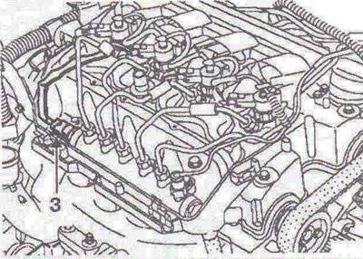
Figure 4.85. Disconnect pressure sensor 3 and wires from the injectors.
15. Disconnect the fuel drain line from the injectors (figure 4.86).
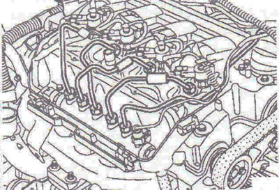
Figure 4.86. Disconnect the fuel drain line from the injectors.
16. Disconnect the high pressure fuel line between the high pressure accumulator and the fuel pump (figure 4.87).
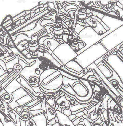
Figure 4.87. Disconnect the high-pressure fuel line between the high-pressure accumulator and the fuel pump.
17. Disconnect the high pressure fuel lines from the injectors (figure 4.88).
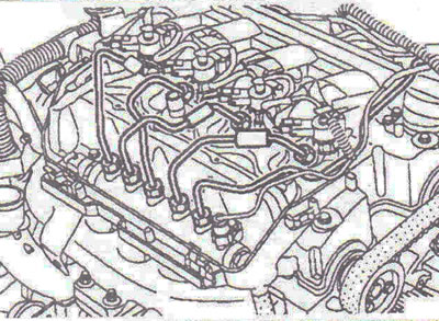
Figure 4.88. Disconnect the high-pressure fuel lines from the injectors.
Caution! When unscrewing the high-pressure fuel line connection nut 4 from the injector holder, hold the support nut 5 with a wrench (figure 4.89).
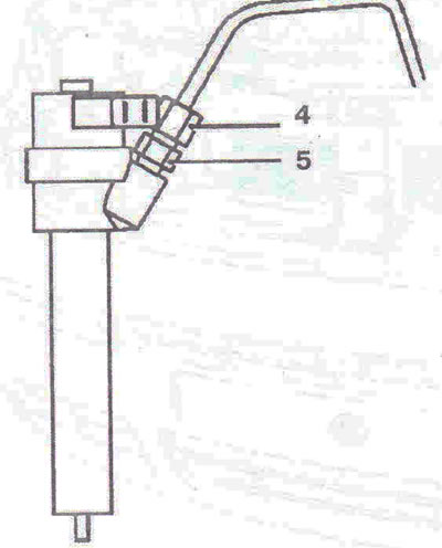
Figure 4.89. When unscrewing the high-pressure fuel line connection nut 4 from the injector holder, hold the support nut 5 with a wrench.
18. Unscrew the high pressure accumulator mounting bolts without removing it (figure 4.90).
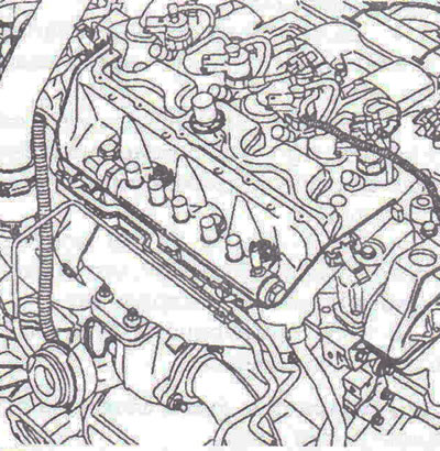
Figure 4.90. Unscrew the high pressure accumulator mounting bolts without removing it.
Removal the injector holders
19. Loosen the mounting bolts of each holder.
20. Using special pliers, remove the injectors. To remove the injectors, use a special tool. Never attempt to remove the injector holder secured to the cylinder head without the special tool described below.
Description of the device Mot. 1549 + Mot. 1730 (figure 4.91a, b).
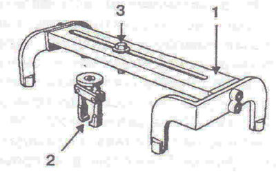
Figure 4.91a. Device Mot. 1549 + Mot. 1730:
1 - Puller support: secured with rocker cover mounting bolts. Please make sure installation is correct before use; 2 - Puller; 3 - Extraction bolt.
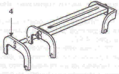
Figure 4.91b. Device Mot. 1549 + Mot. 1730: 4 - Adapter bracket for caliper Mot. 1730.
21. Replace the puller bracket with the caliper bracket Mot. 1730.
22. Apply lubricant to the nozzle.
23. Install the puller on the injector holder (figure 4.92).
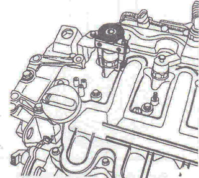
Figure 4.92. Install the puller on the injector holder.
24. Tighten the knurled ring to secure the jaws of the fixture together on two flat surfaces without over-tensioning.
25. Fit tool Mot. 1549 to the rocker cover mounting bolts (figure 4.93).
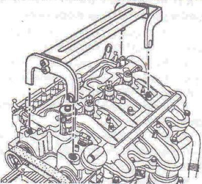
Figure 4.93. Fit tool Mot. 1549 to the rocker cover mounting bolts.
26. Tighten the extraction bolt until the injector is removed from the cylinder head.
27. Remove the washers from the bottom of each injector.
Installation
28. Do not remove protective caps from parts until the last moment.
29. Clean the nozzle holes and body, as well as the brackets, using a lint-free cloth soaked in solvent. Wipe dry with a new cloth.
30. Clean one of the old injector mounting bolts and tighten it to the end of the mounting hole threads to clean the threaded holes.
Caution! Before installing the stud into the cylinder head, make sure that nut 3 is smoothly screwed onto stud 1; if not, replace them (figure 4.94).
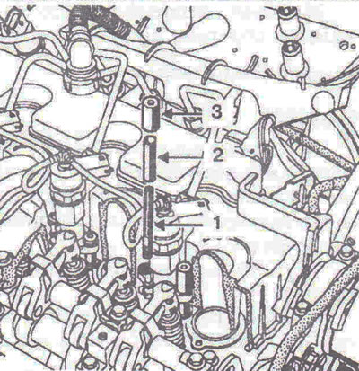
Figure 4.94. Before installing the stud into the cylinder head, make sure that nut 3 is smoothly screwed onto stud 1; if not, replace them.
31. Install new studs 1 and support bushings 2 of the injectors after lubricating the threaded areas with oil and screw them in by hand until they stop (2 Nm) (figure 4.95).
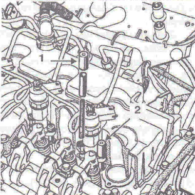
Figure 4.95. Install new studs 1 and support bushings 2 of the injectors after lubricating the threaded areas with oil and screw them in by hand until they stop.
Caution: Studs and nuts must be replaced after each removal.
32. Install new washers on the injector nozzles.
33. Install the injectors with their brackets and locking rings
34. Lubricate the nuts with oil.
Caution! Tighten nut 1 to 6 Nm, then nut 2 to 6 Nm, starting from the timing belt side and then from the flywheel side.
35. Tighten nut 2 to 360" ±30" (flywheel side nut).
36. Loosen the two high pressure accumulator mounting bolts.
37. Connect the high pressure lines.
38. Further installation is carried out in the reverse order of removal.
Injector configuration
IMA code
When replacing one or more injectors and if the IMA function is active, you must program a new calibration for the injector in question.
To ensure that the IMA feature is active:
- select the COMMAND menu, then READ CONFIGURATION (read configuration);
- select line LC041 which shows whether the control unit is equipped with the IMA programming system;
- the injector codes are stored in the control unit memory and are displayed on the Identification screen (Identification) in the Current column of the special command: S0004.
Note: If the saved code is AAAAAAA, there are two possible scenarios:
- 1st: IMA does not work (LC041 =without). Standard display;
- 2nd: IMA works (LC041 = with (c). Go to the procedure for programming the injector code.
In the second case, in line DF173 Injector code programming (Programming the injector code) there is an error. This only happens if the control unit is replaced and if the first control unit did not support the fault finding function (unable to save function: S0005).
The location of the IMA code is shown in the figure 4.96.
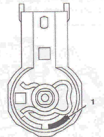
Figure 4.96. IMA code location.
Injector programming procedure
Read the six-digit "alphanumeric" code engraved on the top of the Bakelite body of the injector.
Note: The letters "O" and "J" and the numbers "0" and "9" are not used in the IMA coding. Each code must refer to the cylinder on which the injector is installed.
Select the "COMMAND" menu, then "SPECIFIC COMMAND".
Select line SC004: Enter injection calibration data (Injector calibration data).
Confirm the change of configuration code.
When the command is executed, the modified code will be displayed in the "Current" column.
Make sure all codes match those previously read.
If the entered codes did not appear either in the "current" column or in the "desired" ("desired"), check the codes you read and make sure the data was entered correctly.
Turn off the ignition and wait until the autonomous power supply phase is complete.
Turn the ignition back on and check for faults.
Line DF173: Injector code programming (Programming the injector code) should be "stored" (saved).
If the DF173 line is still present, it means the command was not executed correctly.
Repeat the procedure from the beginning, following the instructions.
Autonomous power supply phase failure
If the fault is still present, this may result in the DF173 line appearing again and the inability to confirm that command SC004 has been executed correctly.
If the independent power supply does not work after the ignition is turned off, the injection system computer will not store new codes. This can happen if the electrical wiring has been changed (installation of alarms or accessories on a car). Check the wiring condition, whether any connections have been made between terminal 3 of the impact sensor and terminal 1 of the control unit main power relay. Repair if necessary.
The autonomous power supply phase is working correctly if the indicator light comes on 2 seconds after the ignition is turned off. If the indicator light comes on immediately after the ignition is switched off, the autonomous power supply phase has not worked and the command will not be taken into account. If after all checks the command is not confirmed, contact the service station.
Visitor comments