


Contents: Introduction ⬇ Checks performed from the driver's…⬇ Checks performed on a vehicle on the…⬇ Checks carried out on a vehicle…⬇ Exhaust gas toxicity test ⬇
Introduction
The Section lists all units and systems subject to inspection and suggests methods for independently checking their condition and functioning. Based on the analysis of the results of such checks, it is possible to assess the vehicle's readiness for operation and technical inspection. Naturally, self-conducted checks cannot be compared in terms of measurement accuracy with professional ones, due to the lack of appropriate operator qualifications and the inaccessibility of special diagnostic equipment. If, during self-checking, it is determined that any component requires repair or replacement, refer to the relevant Sections of the relevant Chapters of the Manual for more complete information.
In most cases, the upcoming checks require the participation of an assistant.
Checks performed from the driver's seat
Parking (hand) brake
The operation of the parking brake is checked by fully cocking its control lever. In this case, you should make sure that the stroke of the lever (number of ratchet clicks), required to create a feeling of full resistance, 4-6 clicks for rear-wheel drive models and 5-7 for all-wheel drive models. If this requirement is not met, the serviceability of the brake mechanisms of the rear wheels of the vehicle and/or the correct adjustment of the parking brake cables should be checked.
With the parking brake fully engaged, rock the control lever from side to side (tap it on the sides) - the brake should not be released, otherwise the ratchet or pawl of the lever will be worn out. Release the parking brake and rock the lever from side to side to check for signs of axle bearing wear. Check the reliability of the lever fastening and make sure that there are no traces of corrosion of the supporting element of the body within a radius of 30 cm around the lever support. If the condition of the control arm fasteners cannot be checked from inside the vehicle, evaluate them later during inspections performed under the vehicle.
Foot brake
Make sure that the brake pedal does not make any sounds when pressed and released, does not show obvious signs of excessive wear of the axle bushings, and also check the condition of the pedal pad. Check for signs of brake fluid leakage on the pedal, floor or surface of the mat around the pedal, indicating a leak in the master cylinder seals.
Press the pedal slowly at first and then quickly, achieving the ability to maintain a steady pressure. Apply pressure and make sure the pedal does not then slowly sink to the floor, which would again indicate a problem with the master cylinder. Release the pedal, wait a few seconds, then press it again until you feel a solid resistance. Make sure that resistance begins to appear already at the top of the pedal stroke. If the pedal needs to be pressed almost to the floor to create resistance, this indicates a problem with the brake adjustment. If there is no solid resistance to pressing the pedal at all, i.e. the pedal stroke is soft, this indicates that air has entered the hydraulic system and the system needs to be completely bled.
The free travel of the pedal should be 3 - 8 mm. Check the proper functioning of the brake booster by pressing the brake pedal several times to release the vacuum. Then, keeping the pedal depressed, start the engine. When the engine starts, the resistance to pressing the pedal should change (decrease). If this is not the case, there is a possibility of "leaks" in the brake booster unit vacuum hoses or its actual malfunction.
The front and rear brakes are equipped with wear indicators that produce a metallic grinding sound when the vehicle is moving with brake pads worn to the maximum permissible thickness.
If this sound occurs, the brake pads must be replaced at a MITSUBISHI service center.
Steering wheel and column
Check the steering wheel for cracks or looseness in the hub, spokes or rim. Rock the wheel from side to side, then up and down in relation to the column. Make sure that there is no play in the wheel on the column, which is evidence of a loose wheel nut or wear of the shaft splines. Continue rocking the wheel as described above, but add a slight left-right rotation. Check for excessive wheel play, which would indicate excessive wear of the upper shaft support bearing, universal joint, or flexible coupling.
Windshield and rear view mirrors
The windshield must not have any cracks or other damage that could significantly limit the driver's field of view or interfere with the operation of the windshield wipers. The presence of small chips left by stone impacts is acceptable. Any kind of stickers and hanging souvenirs should also not restrict the driver's view.
Rear view mirrors must be securely fastened, not damaged and adjustable. The door mirror on the passenger side of the vehicle is not subject to inspection, provided that the rear-view mirror, mounted on the inside of the windshield, is in good working order and can be used.
Seats and seat belts
Note: The following checks apply to both front and rear seat belts.
Carefully inspect the structure of the seat belt material for cuts, signs of severe wear or aging of the material. If inertia-type belts equipped with return devices are installed, pull them completely out of the drum cover when inspecting.
Fasten and unfasten each of the belts, checking that the locking mechanisms are functioning properly (both for latching and for opening) and their reliability. If inertia-type belts are installed, check the proper functioning of the return devices.
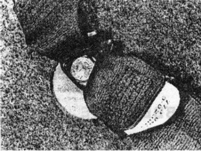
Check the reliability of the fastening of the belts to the body elements and the condition of their support units, which can be accessed without removing the trim panels. The presence of signs of severe corrosion or deformation of the supporting elements of the body within the radius of the belt support is also unacceptable.
Some of the seat belt mounting points are inaccessible and cannot even be visually inspected from inside the vehicle, in which case their condition should be checked later during an inspection of the underbody. If any of the belt mechanism parts are attached directly to the front seat, the seat supports must be securely bolted to the floor and their condition must be checked in the same manner as described above for the belt supports.
The front seats themselves must also be securely fixed and not allow their position to change spontaneously. The backrests must be securely fixed in the vertical position.
Doors
The front doors must be able to be opened and closed from inside the vehicle and must be securely locked in the closed position. On station wagon models, the tailgate must also be securely attached and locked in the closed position.
Electrical equipment
Turn on the ignition and sound the horn. The horn must produce a clear sound that can be clearly heard by other road users. The use of gongs, sirens or 2-tone horns installed as additional accessories by yourself is unacceptable.
Check the operation of the windshield washers and wipers. Washers must deliver a jet of fluid of adequate pressure and flow, and their nozzles must be adjusted so that the jets hit the upper edge of the windshield.
Use the windshield wipers at the same time as the washers and make sure that the blades clean the windshield well throughout their entire range of travel. There should be no streaks or smears of road film on the glass that limit the driver's view in either the straight-line or peripheral sectors of the field of vision. Otherwise, replace the brushes.
Press the foot brake pedal with the ignition on and ask an assistant to check the operation of the brake lights. When you press the pedal, the brake lights should light up, and when you release them, they should go out. If only one of the brake lights does not light up, then the cause of the failure is most likely a burnt-out bulb or poor electrical contact on the bulb socket (or near it). If both brake lights fail, you should check their fuse and switch. The possibility of both lamps burning out simultaneously should not be completely ruled out. Failure of the brake lights to turn off when the brake pedal is released indicates a faulty switch.
Checks performed on a vehicle on the ground
License plates and vehicle identification numbers
Front and rear number plates must be in satisfactory condition, securely attached and easily legible.
The vehicle identification number (VIN), located on the plate under the hood, must be legible.
Electrical equipment
Turn on the parking lights and make sure that both the front and rear parking lights, as well as the license plate lights, are on. Lenses and reflectors must be clean, undamaged and securely fastened. Lens integrity is of particular importance in rear lights, where the white light from a damaged light may be confused with the reversing light signal by other road users. Contamination of the lenses causes a noticeable reduction in the intensity of light emitted by the lamp.
Turn on the headlights and make sure that both the low and high beam units are functioning normally and with the same intensity for both headlights. A decrease in the intensity of the glow of any of the headlights is usually associated with a violation of the quality of electrical contacts or severe corrosion of the internal reflector. Check the headlight lenses for cracks and pits caused by stone impacts. Such defects are unacceptable, but usually the qualification of their severity is a subjective factor. Remember that all lighting fixtures must operate reliably when the switches are first turned on. Tapping on the light unit to turn it on is not permitted.
Headlights must not only be adjusted so as not to blind other road users when in low beam mode, but also provide adequate illumination of the roadway in front of the vehicle. The headlight adjustment is checked using special optical equipment, therefore, if you are not sure that it is correct, you should contact specialists in advance to check and adjust the position of the headlights.
After turning on the ignition, check the operation of the direction indicators. Make sure that both the front and rear ones are emitting a yellow light and flashing at a rate of about one to two times per second. In addition, it is a mandatory requirement that the turn signal indicators on the instrument panel are in good working order. Switching on the side lights and brake lights should not affect the operation of the direction indicators - if this is not the case, the cause is usually poor grounding in the rear combination light units. Likewise, make sure that the hazard warning lights are functioning properly, as they should operate both when the ignition is on and when it is off. Check the condition of the lenses (see above).
Check the operation of the fog lights. The mandatory check usually concerns only the externally mounted fog light, which is included in the standard equipment and is located on one side of the car. The headlight must be securely mounted and produce a bright, sharp beam of red light. Control lamp on the instrument panel (or inside the switch) should also function.
Foot brake
From the engine compartment, check the brake lines for signs of leaks, corrosion, loose fittings, wear, or other damage. Inspect the master cylinder and brake booster assembly for signs of leaks, secure mounting, and signs of excessive corrosion of both component mounts and surrounding bodywork. The master cylinder reservoir must be securely fastened; if it is made of a translucent material, the liquid level in it should be between the upper and lower marks on the walls.
Turn the steering wheel so that the right front brake hose can be inspected. Check the hose carefully for cracks and signs of rubber aging. Defects are most easily detected when bending the hose in half and their presence is almost inevitable in the areas where the hose connects to the fittings. Turn the steering wheel fully left, then fully right, and make sure the hose does not contact the wheel rim, tire, or any moving suspension or steering components. With an assistant pressing the brake pedal hard, check the hose for bulges and signs of fluid leaking under pressure. Repeat the checks for the left brake hose. If defects are detected, make the necessary replacements.
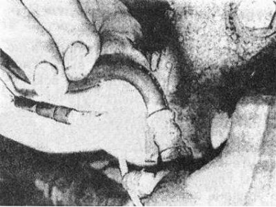
Check brake line tubes and hoses for signs of damage and material aging.
Steering and suspension
Ask an assistant to turn the steering wheel slightly to the right and left in the range until the moment the rotation begins to be transferred to the steered wheels. Try to estimate the amount of free play of the steering wheel before the steering mechanism starts to operate. The amount of play provides information about the degree of wear of the steering column joints, wear and reliability of the fastening of the coupling connecting the column to the steering mechanism or unreliability of the fastening, wear or misalignment of the steering mechanism itself. The steering wheel free play should not exceed 40 mm.
Have an assistant turn the steering wheel vigorously in both directions until the steering wheel begins to turn. At the same time, carefully monitor the behavior of the hinges, rods and other elements of the steering drive and their mounting points. Components showing signs of wear, damage, deformation or poor fastening must be repaired or replaced. If the vehicle is equipped with a power steering system, also check the reliability of the system pump and the condition and correct tension of its drive belt. The system must function properly and show no signs of hydraulic fluid leaks or hose damage. Additional checks can be made later, once the vehicle is raised off the ground and access underneath is much easier.
Make sure the vehicle is level and has the correct ground clearance. Make sure there is sufficient clearance between the suspension components and the compression dampers to ensure full suspension travel.
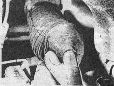
Checking the condition and reliability of fastening of the protective covers of the steering rack.
Shock absorbers
Press on each corner of the car in turn, then release it sharply. If the shock absorber is OK, the angle should rise and then return to normal. If the corner of the car continues to bounce up and down after release, the shock absorber has lost its damping properties.
Exhaust system
Start the engine and, having an assistant press a rag against the end of the exhaust pipe, check the entire system for signs of leaks, which will manifest themselves in the form of rhythmically pulsating streams of smoke or a hissing sound emanating directly from the source of the leak. Check the efficiency of the muffler by making sure that the sound level emitted by the engine is as expected for the type of vehicle. If the system is generally in satisfactory condition, minor local leaks can be repaired using a patented special repair kit.
Checks carried out on a vehicle raised above the ground with wheels rotating freely
Jack up the vehicle, securely supporting it on supports placed under the load-bearing points of the vehicle frame. Install the supports so that they do not come into contact with suspension components (including when turning the front wheels). Make sure all wheels are off the ground and that the steerable wheels can turn from lock to lock.
Steering gear
Check the condition of the rubber protective boots of the steering rack. Make sure there are no cuts, signs of leaks or unreliable fastening of the bandages. If the control is equipped with a power steering system, check its rubber hydraulic hoses, tubes and their joints for signs of material aging, leaks, abrasions and other damage. Carefully inspect all steering components for signs of binding or excessive stiffness, loss of cotter pins or other locking devices, and signs of excessive corrosion of body components within a 30 cm radius around the mounting points of any of the components.
Ask an assistant to turn the steering wheel all the way to the left, then to the right. Make sure that the steering components are in good condition (columns, mechanism and drive) move smoothly and freely and that none of them (including wheels and tires) does not come into contact with hoses or pipes of the brake system or any elements of the vehicle body.
Front and rear suspension and wheel bearings
Starting from the right front, check the condition of the wheel bearings, suspension ball joints, pivot points and suspension component fasteners one by one. To do this, grab the wheel at the 3 and 9 o'clock positions and tug it hard. The presence of any play in the listed units is unacceptable. Check the rubber and metal bushing housings of the suspension components for signs of aging or material damage, and the components themselves for bends, deformations and signs of excessive corrosion. Check that all cotter pins, lock washers or other locking hardware are present on suspension component fasteners. Make sure there are no signs of severe corrosion of body parts within a radius of 30 cm around the attachment points of the components.
The presence of any excessive play can be determined by inserting a pry bar or large screwdriver between the component support and its body and using it as a lever. This will help determine whether the slack is caused by wear on the axle bushing, the mounting bolt, or the pores themselves (bolt holes are often developed to an oval shape).
Now grab the wheel at the 12 and 6 o'clock positions and repeat the check described above. Rotate the wheel to check for any binding points in the bearing.
Repeat the check for the second front wheel, then for both rear wheels.
Springs and shock absorbers
Inspect the suspension strut assemblies for signs of fluid leaks, corrosion, deep piston rod cavities, or damaged housings. Also, make sure that the racks are securely fastened.
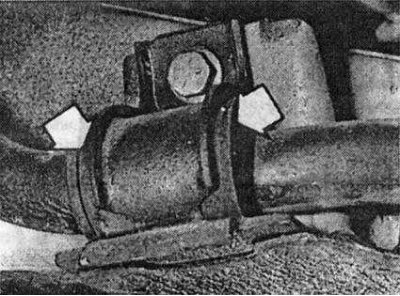
Check the rubber boots of all suspension joints (arrows) for damage and signs of material aging.
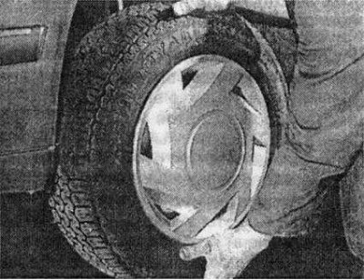
Give the wheel a sharp tug to check for excessive play in the bearings and suspension components. Make sure that the ends of the coil springs are properly seated in their seats and that the spring body rod is not damaged by corrosion, broken, cracked or otherwise defective. Check the reliability of the fastening of the support units, the presence of signs of excessive wear, corrosion, cracks, deformations, and other damage to the components and their bushings. Check for signs of leaks or damage to hoses or tubes (hydraulic type suspensions).
Check your shock absorbers for signs of serious leaks (a small amount of fluid leakage is normal for some types of shock absorbers). Check the fasteners and bushings of the support units for wear and damage to the block housings.
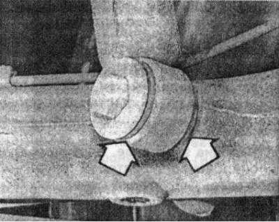
Check the condition of the shock absorber supports and bushings (arrows).
Drive shafts
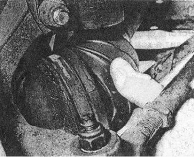
With the steering wheel turned all the way, turn each of the front wheels in turn and inspect the constant velocity joint (CV) boots (where provided) for cracks and other damage. Also check the reliability of fastening the covers to the corresponding housings with your own bandages. While continuing to rotate the wheel, make sure the drive shaft is not bent or otherwise damaged.
Brake system
If possible, without disassembling the mechanisms, check the condition of the brake pads and discs. Make sure that the friction lining material is not excessively worn and that the disc surfaces are free of cracks, cavities, grooves or other signs of excessive wear.
Carefully check the condition of the rigid brake pipes under the car and the flexible hoses of the rear brake mechanisms. The presence of traces of excessive corrosion, abrasions, unreliable fastening of tube fittings, as well as cracks, signs of material aging, leaks and swelling under pressure of flexible hoses is unacceptable.
Check the brake calipers and shields for signs of brake fluid leaks, which indicate a deterioration in the quality of the hydraulic seals of the corresponding components.
While slowly rotating each wheel in turn, ask an assistant to press the foot brake and then release it. Make sure that each brake mechanism is functioning properly and that the wheel rotates freely when the brake pedal is released. It is not possible to check the efficiency of the brake mechanisms without using special equipment, but running tests(subject to appropriate road and weather conditions) are able to detect the effect of a vehicle being pulled to the side when driving in a straight line.
Check the parking brake drive mechanism for frayed or broken cables, excessive wear and unreliable fastening of the rods. After asking an assistant to apply and then release the parking brake, make sure that the brake mechanisms of each of the rear wheels of the car are securely applied and released.
Fuel and exhaust systems
Check the condition of the fuel tank, pipes, hoses and fittings (including connections at pump, filter and carburetor/fuel injection system). All components must be securely fastened and show no signs of leakage. The fuel tank cap must close securely and meet the type requirements of the vehicle manufacturer.
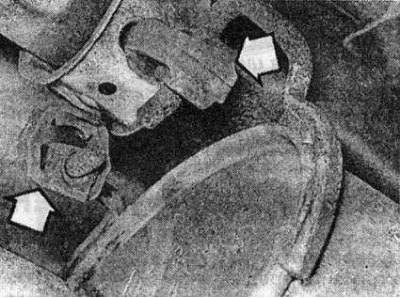
Check the exhaust system along its entire length for damage to supports and suspensions, the reliability of the clamps of the section butt joints, and traces of corrosion.
Wheels and tires
Carefully inspect the tires of all wheels one by one, both from the outside and from the inside, as well as over the entire surface of the tread. The presence of cuts, cracks, swellings, seals, tread delamination, as well as exposure of the cord and tire frame due to wear or damage is unacceptable. Make sure the tire bead fits snugly on the wheel rim. Check the fit and condition of the tire inflation valve (nipple). Rotate the wheels, checking the disks for signs of deformation, especially along the rim.
Make sure that the correct size tires are installed, corresponding to the vehicle make and model. It is not permitted to install tires of different types or sizes on the same axle. It is not permitted to use special spare tires during normal vehicle operation (compact) type. In addition, the tires must be inflated to the required pressure.
Using a special device, measure the depth of the tire tread pattern. According to currently accepted road safety regulations, the pattern must be clearly visible over the entire area of the tread and have a depth of at least 1.6 mm over at least three-quarters of the tread width. A certain amount of tread wear on the outer and inner edges is acceptable, but it must be in the form of an even, continuous ring and the tread pattern on the worn area must also be visible. Any of the above excessive wear may be a sign of front wheel alignment problems, which should be checked before the tires fail completely. For more information on typical tread wear and front wheel alignment, see:. in the relevant Chapters of the Guide.
Body corrosion
Check all load-bearing elements of the vehicle body and frame in areas subject to stress for signs of corrosion. All frame profile elements, thresholds, cross beams, body pillars, supports and fasteners of suspension and steering elements, brake system components and seat belts are considered loaded and load-bearing. Corrosion, which significantly reduces the thickness of the metal of the supporting sections of the car body and causes them to weaken, is unacceptable. In this case, the car must undergo body repair.
Exhaust gas toxicity test
Warm up the engine to normal operating temperature and ensure that the prerequisites for checking the idle speed and mixture quality are met (i.e., that the ignition system is functioning normally and the air filter element is in satisfactory condition).
Before starting the measurements, raise the engine speed to approximately 2500 rpm and hold it there for about 20 seconds. Reduce the speed back to idle and look closely at the smoke coming out of the car's exhaust pipe. If the idle speed is clearly excessive, or if clearly visible dark blue or black smoke is emitted from the exhaust system for more than 5 seconds, the vehicle must be serviced. Blue smoke is a sign of engine oil burning (wear of valve stem oil seals, valve guides, piston rings or cylinder bores), while black can be considered as evidence of incomplete combustion of fuel (dirty air filter element, excessively rich mixture or other problems with the carburetor or fuel injection system).
If the idle speed and external condition of the exhaust are normal, it is necessary to measure the content of carbon monoxide (CO) and hydrocarbon compounds in the exhaust using an exhaust gas analyzer. It is further assumed that such an analyzer can be rented or borrowed - it is irrational for an amateur mechanic to purchase it. Alternatively, you should contact a service station to carry out this check, where the prices for this type of work are usually quite reasonable.
Emission with (quality of the mixture)
When carrying out this check, it is necessary to be guided by the requirements of the traffic regulations regarding the CO content in exhaust gases.
If it is not possible to reduce the CO level to within acceptable limits (it is assumed that from other points of view the fuel and ignition systems are functioning properly), it is necessary to assume the presence of severe wear of the carburetor or some defect in the fuel injection system. On carburetors equipped with automatic starting, it is possible that the air damper does not release properly.
It is possible that the CO level meets the traffic regulations but exceeds the standard set by the manufacturer.
Emission of hydrocarbon compounds
After making sure that the CO level in the exhaust gases is normal (or achieve this), proceed to measuring the content of hydrocarbons in the exhaust. It should not exceed 1200 parts per million. If the vehicle fails this test at idle, repeat the test at 2000 rpm; if the hydrocarbon content now falls within the norm, the test can be considered successfully passed.
Excessive levels of hydrocarbon compounds in exhaust gases may be a sign of oil burnout, but with no less probability it can also be caused by incomplete combustion of fuel. Possible reasons may include:
- a) Poor condition of spark plugs or incorrect spark plug gap.
- b) Violation of the ignition timing angle setting.
- c) Incorrect valve clearance.
- d) Low compression pressure in the cylinders.
Also remember that excessive hydrocarbon content in the exhaust gases may be a consequence of malfunctioning of the catalytic converter (if such is included in the vehicle's equipment).
Visitor comments