OpelBook.ru
Cars AvtoVAZ Cars Mitsubishi Cars BMW Cars Mercedes Cars Nissan Cars Toyota Cars Chevrolet
English Русский
Български
Беларускі
Український
Српски
Hrvatski
Română
Polski
Slovenský
Magyar
 |  Sitemap  |  Contacts  |    


Main Astra Corsa Insignia Kadett Omega Vectra Zafira Others Articles
Astra F (1991-1998, petrol) Astra G (1998-2004, petrol) Astra G (1998-2004) Astra H (2004-2009) Astra J (2009-2015, petrol)
  • Main
  • Astra
  • Astra G
  • Electrical equipment
  • Equipment and devices
  • Removal and installation SRS components

Removal and installation SRS components (Opel Astra G)

            0

Contents: Front driver airbag ⬇ Front passenger airbag ⬇ Side airbags ⬇ Airbag contact drum on steering…⬇ Electronic control unit ⬇ Door shock sensors ⬇ Front passenger seat occupancy sensor ⬇
Before servicing any SRS components, read the safety precautions (see Supplemental Restraint System (SRS) - General Information!


Front driver airbag


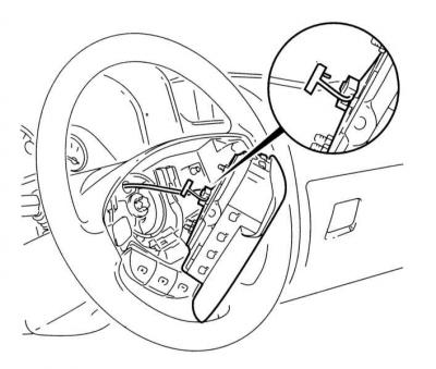
The front driver's airbag is built into the steering wheel hub and is located below the horn activation button.

1. Disable SRS (see Vehicle Speed Sensor (VSS) - General Information).

2. Set the front wheels to the straight-ahead position. Remove the key from the ignition and lock the column.

3. Remove the two mounting screws at the rear of the steering wheel and carefully remove the airbag module assembly with the horn button trim.

4. Disconnect the electrical wiring from the airbag module. Store the removed module in a safe place and place it face up.

4. Disconnect the electrical wiring from the airbag module. Store the removed module in a safe…


When carrying the module, hold it with the faceplate away from you!


5. Installation is carried out in the reverse order. Do not forget to restore the original wiring connection, make sure that the mounting screws are tightened with the required force.


Front passenger airbag


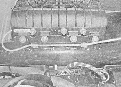
The passenger airbag is attached to the crossbar under the vehicle's instrument panel.

1. Disable SRS (see Vehicle Speed Sensor (VSS) - General Information).

2. Remove the glove box (see Chapter Body).

3. Using a TORX key, loosen the mounting bolts and remove the airbag module from the support bracket on the crossmember.

3. Using a TORX key, loosen the mounting bolts and remove the airbag module from the support…


4. Disconnect the wiring and remove the module from the vehicle - note that the underside of the unit is machined to fit into the bracket holes.
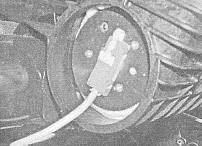
4. Disconnect the wiring and remove the module from the vehicle - note that the underside of the…


5. Installation is carried out in the reverse order. Make sure that the mounting bolts are tightened to the required force.

Side airbags


Side airbags are mounted on the outer sides of the front seat backs.

1. Disable SRS (see Vehicle Speed Sensor (VSS) - General Information).


2. Release the fasteners and remove the side decorative trim from the seat back.

3. Disconnect the electrical wiring from the module.

4. Loosen the three mounting nuts and remove the cushion from the seat back

Manufacturers recommend replacing the self-locking nuts that secure the airbag modules without fail.


5. Installation is carried out in the reverse order. Correctly connect the wiring and tighten the nuts to the prescribed torques.

Airbag contact drum on steering column


1. Remove the driver's airbag module (see above).

2. Remove the steering wheel (see Chapter Suspension and steering). Make sure the front wheels of the vehicle are in the straight-ahead position, the ignition key is removed from the lock and the steering column is locked.

3. Remove the mounting screws and remove the upper and lower sections of the steering column cover (see Chapter Suspension and steering). Remove the cover with the key position identification marking from the ignition switch.

4. Using a small screwdriver, release the retainer and latch and disconnect the wiring connector from the back of the contact block.

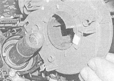
5. Release the four rear fasteners and remove the contact block from the top of the steering column.

5. Release the four rear fasteners and remove the contact block from the top of the steering column.


Make sure that both halves of the contact block remain in the central position with the arrows facing down - secure them with tape if necessary.


6. Before installing a new contact drum, or an old one with a disturbed centering, press the upper lock and carefully rotate the upper part of the block counterclockwise until you feel resistance. Now turn the block 2.5 turns clockwise and achieve alignment of the arrows on the central section and the outer edge. When installing a new block, first remove the transport fasteners.

7. Install the contact drum on the steering column, making sure that the guide pins are correctly positioned in the holes in the steering column. Press the unit until the locks click into place.

Be extremely careful - if the fasteners are damaged, the unit must be replaced as a whole!


8. Restore the original wiring connection and secure the connector with the lock.

9. Install the ignition switch cover with the key position identification marking. Install the steering column cover sections and securely tighten the screws (see Chapter Suspension and steering).

10. Install the steering wheel (see Chapter Suspension and steering).

11. Install the airbag (see above).

Electronic control unit


1. Turn off the system (see Vehicle Speed Sensor (VSS) - General Information).

2. Remove the center console (see Chapter Body). On zafira models also remove the gear shift lever assembly (see Chapter Manual gearbox), - the control unit is located under the lever.
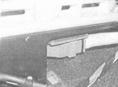
2. Remove the center console (see Chapter Body). On zafira models also remove the gear shift lever…


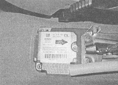
3. Disconnect the wiring from the unit, loosen the mounting nuts and remove the unit from the car - note that the arrow on top of the unit should point forward along the car (due to the asymmetrical arrangement of the fasteners, the block has a unique installation position).


3. Disconnect the wiring from the unit, loosen the mounting nuts and remove the unit from the car -…


4. Installation is carried out in the reverse order. Make sure that the fasteners are tightened with the required force.

When installing a new control unit, it must be programmed in an Opel branded car service workshop.


Door shock sensors


The sensors are installed inside the front doors.

1. Turn off the system (see Vehicle Speed Sensor (VSS) - General Information).

2. Remove the inner door trim panel (see Chapter Body).

3. To provide access to the sensor, bend back the plastic insulating membrane.

4. Remove the mounting screws and remove the sensor from the support bracket. Disconnect the electrical wiring.

5. Installation is carried out in the reverse order. Make sure that the fasteners are tightened securely.

Front passenger seat occupancy sensor


The sensor is built into the seat cover. The replacement procedure should be entrusted to car service specialists.


This article is available at russian, bulgarian, belarusian, ukrainian, serbian, croatian, romanian, polish, slovak, hungarian
Checking the article: Pavlovsky Nikolay

Share information:

Previous articles
Opel Astra G: Equipment and devices
Next articles

Supplemental Restraint System (SRS)
Vehicle Speed Sensor (VSS) — General Information
Anti-theft and engine immobilization system — general information
Removal and installation the radio antenna
Removal and installation speakers
Removal and installation remote control elements for the audio system


See similar ones from other Opel car manuals:
▶ Checking the status of components Opel Corsa B (1993-2000)
▶ Precautions to prevent the collapse of the vehicle or its… Opel Insignia A (2008-2017)
▶ Distinctive components of the Motronic ML4.1 system from… Opel Kadett E (1984-1995)
▶ Engine Components — Inspection and Refurbishment Opel Omega A (1986-1993)
▶ Rear Ride Control Components — Removal and Installation Opel Vectra A (1988-1995, petrol)
Link to this page in different formats

Visitor comments


No comments yet


How much will 21 + 12 =


Astra J (2009-2015, petrol) 
  • General information
  • Vehicle device
  • User manual
  • Faults en route
  • Maintenance
  • Power unit
  • Engine repair
  • Cooling and lubrication system
  • Engine power system
  • Exhaust system
  • Transmission
  • Clutch
  • Car gearbox
  • Drive shafts
  • Chassis
  • Front suspension
  • Rear suspension
  • Steering
  • Brake system
  • Wheels and tires
  • Body
  • Exterior
  • Interior
  • Doors and windows
  • Body Care
  • Heating and air conditioning
  • Security systems
  • Electrical equipment
  • Equipment and devices
  • Lighting and signaling
  • Power devices
  • Electrical circuits
Astra H (2004-2009) 
  • General information
  • Introduction to the guide
  • Troubleshooting
  • User manual
  • Maintenance
  • Power unit
  • Engine repair
  • Cooling and heating
  • Power and exhaust system
  • Ignition system
  • Launch and charge system
  • Transmission
  • Mechanical gearbox
  • Automatic gearbox
  • Drive shafts
  • Chassis
  • Brake system
  • Car suspension
  • Steering
  • Body
  • Interior
  • Exterior
  • Electrical equipment
  • Equipment and devices
  • Electrical circuits
Astra G (1998-2004) 
  • General information
  • Introduction to manual
  • User manual
  • Maintenance
  • Power unit
  • SOHC gasoline engines
  • DOHC gasoline engines
  • Diesel engines 1.7 and 2.0
  • Engine repair
  • Cooling system
  • Supply system
  • Injection system (gasoline)
  • Injection system (diesel)
  • Exhaust system
  • Charge and launch system
  • Ignition system (gasoline)
  • Preheat system (diesel)
  • Transmission
  • Manual gearbox
  • Automatic gearbox
  • Clutch
  • Drive shafts
  • Chassis
  • Brake system
  • Wheel suspension
  • Steering
  • Body
  • Exterior
  • Interior
  • Doors and windows
  • Ventilation and heating
  • Electrical equipment
  • Equipment and devices
  • Electrical circuits
Astra G (1998-2004, petrol) 
  • General information
  • User manual
  • Car care
  • Maintenance
  • Power unit
  • Single shaft engines
  • Twin shaft engines
  • Engine repair
  • Cooling and heating
  • Fuel and exhaust systems
  • Starting and charging system
  • Ignition system
  • Transmission
  • Clutch
  • Mechanical gearbox
  • Automatic gearbox
  • Drive shafts
  • Chassis
  • Brake system
  • Car suspension
  • Steering
  • Body
  • Interior
  • Exterior
  • Electrical equipment
  • Equipment and devices
  • Wiring diagrams Opel Astra
  • Wiring diagrams Opel Zafira
Astra F (1991-1998, petrol) 
  • General information
  • Maintenance
  • Power unit
  • Engine in car
  • Engine removed
  • Cooling system
  • Heating and ventilation
  • Fuel supply (carburetor)
  • Fuel supply (injector)
  • Emission control
  • Ignition system
  • Transmission
  • Clutch
  • Mechanical gearbox
  • Automatic gearbox
  • Drive shafts
  • Chassis
  • Brake system
  • Car suspension
  • Steering
  • Body
  • Exterior
  • Interior
  • Electrical equipment
  • Equipment and devices
  • Electrical circuits
OpelBook.ru © 2017–2026 · Mobile version · · Sitemap: EN BG BY UA RS HR RO PL SK HU · Feedback · Site search
Astra F, petrol · Astra G, petrol · Astra G · Astra H · Astra J, petrol · Corsa B · Corsa C, petrol · Corsa C · Insignia A · Kadett D · Kadett E · Omega A · Omega B · Omega B2 · Vectra A, petrol · Vectra A · Vectra B, petrol · Vectra B · Vectra C · Zafira A, petrol · Frontera A, petrol · Frontera B · Ascona C · Vivaro A ·
We want your visit to be comfortable 🤝! We use cookies 🍪 to make that happen.