
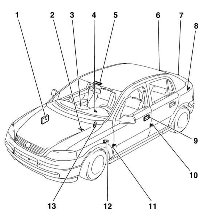
1 - Control unit
2 - Contact sensor hood
3 - LED on the alarm switch
4 - Ignition lock
5 - Ultrasonic sensor in the saloon lamp
6 - Rear window status sensor (a heating element)
7 - Contact sensor tailgate / luggage compartment lid
8 - Luggage compartment lighting
9 — the Cylinder of the lock of a driver's door
10, 11 - Sensors-switches for interior lighting / threshold lighting when opening doors
12 - Additional siren
13 - Main siren
See also the information given in Chapter Manual.
General information
All models are equipped with an immobilization device that effectively prevents unauthorized attempts to start the engine. The system is activated by the ignition key and an electronic sensor built into the ignition lock.
The anti-theft system control unit monitors the status of all doors, including the tailgate / tailgate, hood and ignition lock, as well as interior and luggage compartment volumes and vehicle roll using contact and volumetric sensors (see illustration The layout of the elements of the anti-theft system). The control unit is installed at the bottom of the right front pillar at the passenger's feet and is covered with a decorative panel. Ultrasonic (voluminous) sensors are installed in the upper part of the central pillars and react to any changes in the interior volume. Tilt sensors respond to changes in vehicle roll even when trying to remove the wheel. The main signal siren of the anti-theft system is installed on the left on the bulkhead of the engine compartment under the hood, an additional siren is installed under the left front fender. On Universal and Zafira models, the glass condition sensor is installed in the luggage compartment, closer to the rear side window.
Removing
Before removing any component of the anti-theft system, you must disconnect the negative cable from the battery.
Engine/transponder immobilization unit
1. Remove the steering wheel and steering column cover (see chapter Suspension and steering). On models equipped with a latch block, remove the lock cylinder (see Removal and installation of switches), then remove the block from the lock body and disconnect the wiring. On models with a block without latches, disconnect the electrical wiring, then remove the block from the ignition lock housing.
When installing a new unit, it must be programmed using special equipment in a car service workshop.
Hood contact sensor
1. Turn out two fixing screws, remove the sensor and disconnect from it electroconducting.
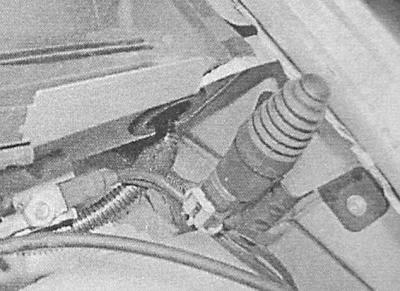
Main siren
1. To remove the emitter, remove the water-reflecting plate from the bulkhead of the engine compartment, release the fixing nut and disconnect the electrical wiring.
Additional siren
1. Remove the left front wheel arch protection locker (see chapter Body), disconnect the electrical wiring, unscrew the mounting bolts and remove the siren from the wing mudguard assembly with the support bracket.
Door contact
See Removal and installation of switches.
Single lock components
see chapter Body.
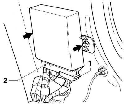
Anti-theft control unit and a single lock
1. Turn out the fixing screw and remove the lower decorative panel of the right forward rack, then remove the lateral panel of finishing of a foot well. Disconnect the electrical wiring, give two fixing nuts and remove the control unit.
Remote control battery
For a description of the procedure for replacing the remote control battery, see Chapter Manual.
Installation
Installation of all components is carried out in the reverse order of their dismantling. Elimination of any malfunctions in the system must be carried out in the conditions of a service station.
Visitor comments