
Ignition lock / Steering column lock
Steering column lock cylinder
1. Remove the steering wheel (see chapter Suspension and steering), - do not forget to first disconnect the battery.
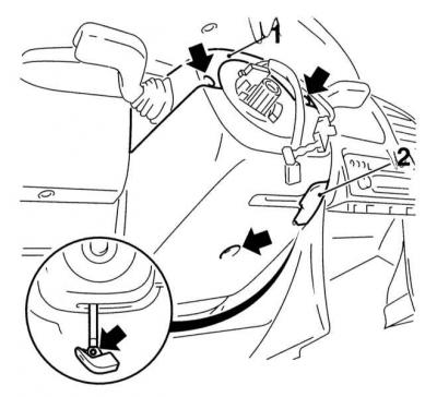
2. Turn out fixing screws and remove sections of a casing of a steering column, remove the handle of the lever of adjustment of provision of a column.
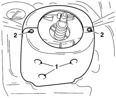
A — Screws of fastening of casings of a steering column (Astra models)
B — Screws of fastening of a casing of a steering column (Zafira models)
A.

B.
3. Remove the right stalk from the column (see below). If necessary, remove the immobilization system transceiver from the ignition lock, disconnect the electrical wiring from the transceiver.
4. Insert the ignition key and turn it to the I.
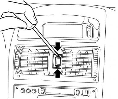
5. With a watch screwdriver or a blunt awl, press the latch through the hole in the upper part of the steering column and, pulling the key, remove the lock cylinder.
6. To install the cylinder, push it into the body of the lock assembly until the latch snaps into place, then turn the key to the position 0 and extract it. When the steering column is locked, it will not be possible to install the cylinder; in this case, the locking pin in the lock housing must first be pressed down with a screwdriver.
Ignition switch
1. Remove the lock cylinder (see above), or insert the key into the lock and turn it to the 0.
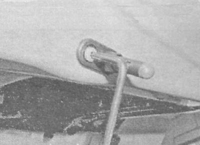
2. Insert a clock screwdriver into the hole in the bottom of the switch and wring out the internal latch, then, prying with a second screwdriver, disconnect the electrical wiring connector.
3. Having disconnected the connector, release the fasteners and remove the ignition switch (contact group).
4. Installation is carried out in the reverse order.
Paddle switches
1. The removal of both steering column switches is carried out according to a single scheme.
2. Remove the steering wheel (see chapter Suspension and steering), - do not forget to first disconnect the battery.
3. Release fastener of the lever of a drive of the mechanism of adjustment of position of a steering column, turn out fixing screws and remove the top and bottom sections of a casing of a steering column.
A — Screws of fastening of casings of a steering column (Astra models)
B — Screws of fastening of a casing of a steering column (Zafira models)
A.
B.

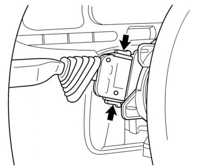
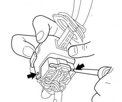
4. Squeeze the locking tabs located at the edges of the assembly and carefully separate the switch block from the steering column.
5. Disconnect the wiring and remove the switch. Disconnect the electrical wiring from the control panel for the operation of the tempostat, if equipped accordingly.
6. Installation is carried out in the reverse order.
Switches for controlling the functioning of outdoor lighting devices
1. Using a small screwdriver, release the latches and remove the light control switch.
2. After inserting a pair of small screwdrivers into the hole for the switch installation, release the latches and remove the switch panel - note that the electrical wiring connector remains inside the instrument panel.
3. If necessary, replace the backlight (see Section Replacing interior lighting bulbs).
4. Installation is carried out in the reverse order.
Hazard switch
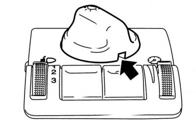
1. Gently prying off with a screwdriver, remove the facing of the alarm pushbutton switch.
2. After passing two screwdrivers into the channels on the sides of the button, carefully release it from the instrument panel.
3. Install in reverse order
The switch of a choice of the high-speed modes of functioning of the fan of a heater
1. Remove the heating/ventilation/air conditioning control panel (see chapter Cooling, heating systems).
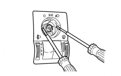
2. Gently prying off the rotary knob for selecting fan speeds from the panel.
3. Release the four latches and press the switch on the back of the panel.
4. Installation is carried out in the reverse order.
Sensors-switches of stoplights and a control lamp of a cocking of a parking brake
see chapter Brake system.
Sensors-switches for interior lighting / sill lighting when opening doors and luggage compartment lighting
1. Turn out the fixing screw and remove the sensor-switch.
2. Disconnect the electrical wiring and fix the harness on the rack with tape. When removing the sensor-switch of the tailgate, it is easier to first remove the internal decorative trims and disconnect the electrical wiring from the sensor-switch.
3. Check the reliability of the contact of the fixing screw with the metal of the body and the sensor-switch, - if necessary, clean the contact patch.
4. Installation is carried out in the reverse order.
The switch of management of functioning of the electric drive of the top hatch
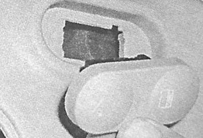
1. Remove the front cabin light (see Section Replacing interior lighting bulbs).
2. Turn out screws of fastening to a ceiling of the control panel of operation of the electric drive of the top hatch.
3. Remove the control panel and disconnect the electrical wiring from the key switch.
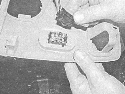
4. Remove the switch from the panel.
5. Installation is carried out in the reverse order.
Visitor comments