
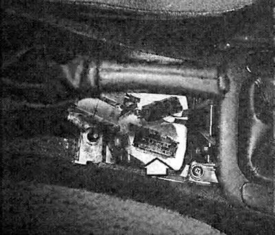
Our Vectra diagnostic connector (arrow) located in the middle console. After removal of facing under the handle of a manual brake the diagnostic socket is visible.
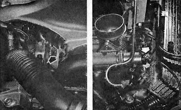
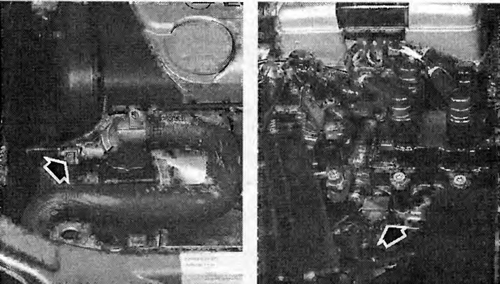
Fuel pressure test: at the test connector photographed here (left 16V 1.6 l, right 16V 1.8/2.0 l) workshop using measuring equipment checks the fuel pressure. If you need to work on the fuel system, then using this valve you can relieve the pressure in the pipelines. To do this, press the valve lifter with a screwdriver - keep a rag ready.
Tip: In all work, you must remember that the fuel system is under high pressure for a long time after the engine has been switched off. Therefore, always relieve pressure through the test fitting on the distribution line before working on the fuel system.
Fuel pressure check
An accurate check of the fuel pressure can be carried out using measuring equipment in the workshop.
Connect a tester to the fuel distribution line test connector.
Disconnect the vacuum hose at the fuel pressure regulator and close with a suitable plug.
Start the engine and remove air from the control device.
Read the measured value on the control device.
Required value 3.0±0.2 bar.
Checking the injectors
If there is a suspicion that one of the nozzles is not working, then you can first try to find it by feeling it with your hand. Unlike the others, a non-working nozzle does not vibrate. Although this check cannot be carried out on all injection systems due to their unavailability.
Deeper checks require a voltage indicator with LEDs and an accurate ohmmeter.
Voltage test: expose the connecting wire to the injectors, see section «Dismantling the nozzles».
Where there is, open the box with wires above the injectors.
Insert two thin needles into the connecting wires of the injector to be checked. Connect the voltage indicator LED to the needles (do not use a test lamp!).
Start the engine: the voltage indicator LEDs should flash, otherwise the voltage is not supplied or the control unit connecting to the ground is faulty. This test cannot be carried out with a measuring device.
Resistance test: expose the connecting wire to the injectors, see section «Dismantling the nozzles».
Loosen the fastening clips on the injectors and, where present, remove the cable channel from the injectors.
Connect an ohmmeter to both valve contacts. With a cold engine (control temperature around 20°C) the measuring device should show from 15 to 17 ohms.
If the value is out of tolerance, replace the nozzle.
Leak test: dismantle the fuel distribution line together with the injectors, the fuel lines remain connected.
Paralyze the ignition, see chapter «Ignition system».
Have an assistant turn the ignition on and off briefly to start the fuel pump and raise the fuel pressure.
Watch the injectors: each individually should release a maximum of two drops of gasoline per minute. Otherwise, replace the nozzle.
Regardless of this, it is possible to check the injection jet and the tightness of the valve, if this is required by engine malfunctions.
Checking the injection jet: dismantle the fuel distribution line together with the injectors, the fuel lines remain connected.
Where there is, reinstall the box with wires on the injectors.
Tightly cover the injector holes in the intake manifold.
Place a clean cloth under the nozzles.
Have your assistant turn the engine over with the starter.
Each nozzle must spray a uniform conical jet.
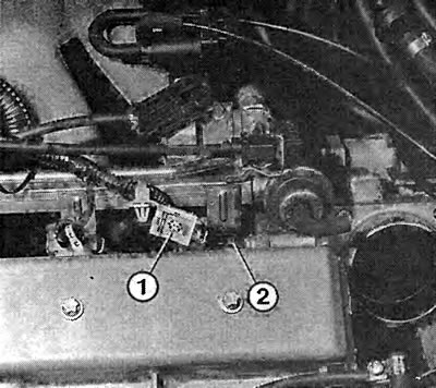
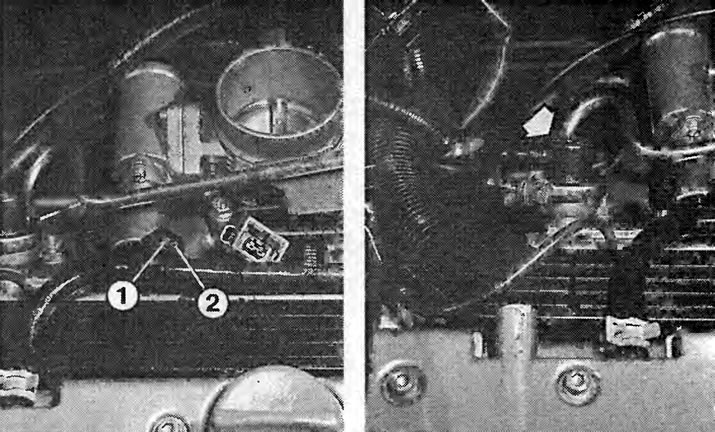
After unplugging the wires (1) on the 16V 1.6l engine or after opening the cable duct on the 16V 1.8/2.0l engine, you can check the voltage supply to the injection valves with the LED indicator (2).
Checking the Multec-S Throttle Potentiometer
You can test the throttle potentiometer yourself as follows:
Open the throttle potentiometer.
Disconnect the potentiometer connectors.
Connect an ohmmeter to the contacts to be tested (pole designation printed on the potentiometer).
If the specified values are not obtained, replace the potentiometer.
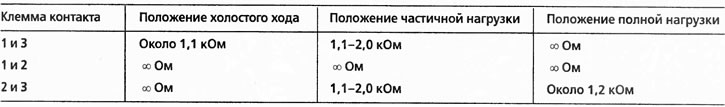
Checking the Simtec Throttle Potentiometer
You can test the throttle potentiometer yourself as follows:
ADD
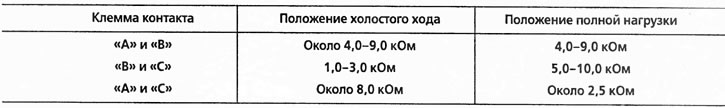
up to 2 kOhm. Just before the full opening angle, the instrument will display ∞ Ohm.
Carry out measurements on other contacts, see the table.
If the specified values are not obtained, replace the potentiometer.
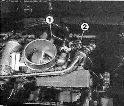
The photo shows the Simtec injection system of the 16V 1.8 / 2.0 liter engine. Numeric «1» throttle potentiometer. «2» - disconnected wire connector.
Left: Checking the idle speed controller: disconnect the wire connector on the idle speed controller and connect the 6V charger in turn to the terminals «1» And «2». The pusher should extend and retract. The photo shows a 16V engine idle speed regulator.
On right: Fuel pressure control (arrow) ensures constant fuel pressure. The photo shows a 16V 1.8 / 2.0 l engine pressure regulator.
Checking the idle speed controller
Remove the idle speed controller.
Disconnect the connector at the idle speed control.
The idle air control piston can be easily inserted and withdrawn with a light touch of the hand.
Switch the charger to bV, and with the Multec-S ignition system, connect in turn to the terminals «A» And «IN» or «WITH» And «D» With the Simtec ignition system, connect the charger in turn to the terminals «1» And «2». The pusher should extend and retract.
If so, then the idle speed control is good. If not, replace it.
Anyone who does not trust the result, then with the Multec-S ignition system can check the resistance of the regulator winding between the terminals «A» And «IN» or «WITH» And «D». It should be 55-65 ohms (regulator cold) or 45-60 ohm (regulator hot).
If a new regulator is installed, make sure that the distance between the end of the pusher and the body flange is not too large. If necessary, gently press the pusher in.
Insert bolts with safety mass and tighten.
Checking the coolant temperature sensor
With a built-in thermometer, you can check if the temperature sensor is working properly. The sensor in cars with Simtec is located on the ignition module DIS, and in cars with Multec-S - on the thermostat housing.

Disconnect the wire connector on the temperature sensor and unscrew the sensor. To do this, with Simtec, unscrew the DIS ignition module. Collect the escaping coolant in a container.
Hang the sensor in a pot of water, heat the water and connect an ohmmeter to the connector pins.
Check the respective resistance values at the above temperatures.
If the values match, then the temperature sensor is OK.
Checking the intake air temperature sensor
The intake air temperature sensor is checked in the same way as the coolant temperature sensor.

Remove the sensor to check. To do this, disconnect the wire connectors on the temperature sensor.
Remove or unscrew the temperature sensor from the air sampling hose.
Observe installation position (Simtec): The flat side of the sensor must match the flat side on the air intake hose. With Multec-S, slide the rubber ring over the sensor and mount the sensor.
Checking the pressure sensor in the intake manifold Multec-S
The Opel workshop uses a special vacuum pump to accurately check the intake manifold pressure sensor.
Connect a voltage indicator to the intake manifold pressure sensor. To do this, stick the needle into the green wire (terminal «IN»). Make sure the needle does not hit bare metal (to ground).
Left: Here we have labeled the terminals of the hot film air mass meter multi-pin connector.
On right:The photo shows the air pressure gauge in the intake manifold of a 16V 1.6L engine with a Multec-S injection system next to the brake booster. Read about the problem he solves in the text on page 88.
Connect the positive terminal of the voltage indicator to the needle. Attach the negative terminal to ground.
Turn on the ignition.
The voltage indicator should show 4.2-5.3 V.
Start the engine and let it idle.
Voltage indicator now shows 0.52-1.7V
Raise your revs. The voltage value changes alternately up and down.
If the values match, then the intake manifold pressure sensor is OK.
Checking Simtec Hot Film Air Mass Meter
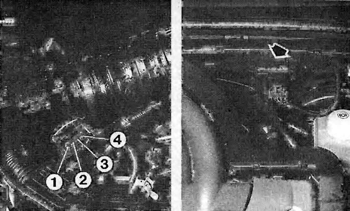
The hot film air mass meter has four connection terminals (wire colors see section «Electrical circuits»): «3» - voltage supply, «1» - ground connection «2» And «4» - signal wires.
In fact, it is reasonable to measure the voltage supply only between the terminal «1» And «3». There should be battery voltage when the ignition is on. If not, the feed is aborted. Do not disconnect the measurement connectors, but «grab» measuring needle.
To check the operation with the engine running at different speeds, a voltage value of different heights must be set on the terminal «2» And «4», which Opel does not provide information about.
At idle (the engine is warm) this value should be 0.25-0.67 V.
Checking lambda control
For these purposes, a voltage indicator with a corresponding low measurement range is used, such as electronics enthusiasts have.
Checking the voltage supply to the lambda probe: disconnect the lambda probe wire connector on the right rear on the gearbox flange. Connect a voltage tester between the brown/grey signal wire (Multec-S) or yellow wire (Simtec) and mass.
Turn on the ignition. The voltage indicator should show 0.4-0.5 V. If the device does not show anything, then check the wire to the control unit along its entire length.
Checking the lambda probe: reconnect the wire connectors.
Warm up the engine.
Insert the needle into the signal wire of the probe. Connect a voltage indicator between the needle and ground.
The coolant temperature sensor informs the injection system control unit of the current coolant temperature. The photo on the left shows a 16V 1.6L engine temperature sensor. The engine temperature sensor 16V 1.8 / 2.0 l is visible on the right.
Make sure that the needle does not hit the mass (short circuit danger).
Accelerate the engine to approximately 1500 rpm.
The voltage indicator should show short, uniform voltage fluctuations between 0.1 and 0.9 V.
If only slow voltage fluctuations are observed, then the heating of the lambda probe or its power supply wire is faulty
No voltage fluctuations: defective lambda probe (replace), too lean or too rich working mixture is constantly supplied (check the injection in the workshop), or the control unit is faulty (check in workshop).
Checking the heating of the probe: Disconnect the wire connector of the lambda probe. Connect a voltage indicator between the voltage supply wire (red/blue wire) and weight (brown/grey wire) probe heating
Checking the heating of the probe: Disconnect the connector from the lambda probe. Connect a voltage indicator between the voltage supply wire (red/brown) and earth wire (brown/grey) heating supply to the probe.
Start the engine. The voltage indicator should show 12 V. If the voltage supply and ground connection are OK, but only slow voltage fluctuations are still observed (see previous text), only the heating of the probe itself remains a possible source of malfunction.
No voltage for heating: Check the voltage supply from terminal 87 of the fuel pump relay.
Tip: The main condition for a functioning lambda control is the correct basic idle setting, i.e. the CO content must be correct, otherwise the control will always be at one end of the control range. The same conditions arise if the working mixture is greatly depleted due to side air.
Visitor comments