
OpelBook.ru
Cars AvtoVAZ Cars Mitsubishi Cars BMW Cars Mercedes Cars Nissan Cars Toyota Cars Chevrolet
English Русский
Български
Беларускі
Український
Српски
Hrvatski
Română
Polski
Slovenský
Magyar
 |  Sitemap  |  Contacts  |    


Main Astra Corsa Insignia Kadett Omega Vectra Zafira Others Articles
Frontera A (1991-1998, petrol) Frontera B (1998-2004) Ascona C (1981-1988) Vivaro A (2001-2014)
  • Main
  • Opel
  • Vivaro A
  • Power unit
  • Diesel engine F9Q
  • Removal and installation the high pressure fuel pump

Removal and installation the high pressure fuel pump (Opel Vivaro A)

            0

Contents: Removal ⬇ Installation ⬇
Attention! Disassembling the fuel injection pump is prohibited.


Removal


1. Place the vehicle on a two-post lift.

2. Disconnect the battery and wiring harness 1 from the heater (figure 3.82). Unscrew the bolt and three nuts 2 securing the heater and remove it.
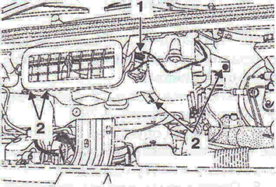
Figure 3.82. Disconnect the battery and wire harness 1 from the heater. Unscrew the bolt and three…

Figure 3.82. Disconnect the battery and wire harness 1 from the heater. Unscrew the bolt and three nuts 2 securing the heater and remove it.


3. Disconnect wiring connector 3 from the air flow meter, pipeline 4 from the turbocharger, unscrew bolts 5 securing the air filter housing and remove the air filter (figure 3.83).
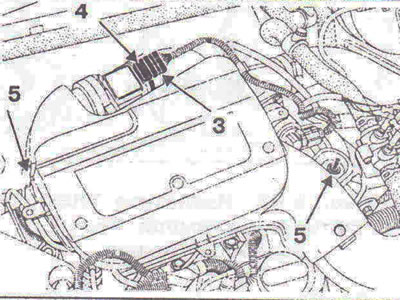
Figure 3.83. Disconnect wiring connector 3 from the air flow meter, pipeline 4 from the…

Figure 3.83. Disconnect wiring connector 3 from the air flow meter, pipeline 4 from the turbocharger, unscrew bolts 5 securing the air filter housing and remove the air filter.


4. Unscrew the 6 bolts securing the radiator grille and remove it (figure 3.84).
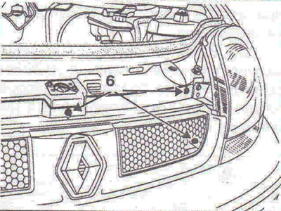
Figure 3.84. Unscrew the bolts 6 securing the radiator grille and remove it.

Figure 3.84. Unscrew the bolts 6 securing the radiator grille and remove it.


5. Disconnect the headlight wiring connectors.

6. Unscrew the two bolts 7 securing the headlights and remove them (figure 3.85).
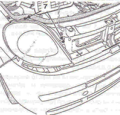
Figure 3.85. Unscrew the two bolts 7 securing the headlights and remove them.

Figure 3.85. Unscrew the two bolts 7 securing the headlights and remove them.


7. Remove the hood lock 8, unscrew the bolts 9 securing the bumper (figure 3.86).
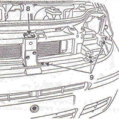
Figure 3.86. Remove the hood lock 8, unscrew the bumper mounting bolts 9.

Figure 3.86. Remove the hood lock 8, unscrew the bumper mounting bolts 9.


8. Disconnect air ducts 10 from the charge air cooling radiator (figure 3.87).
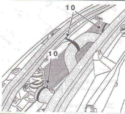
Figure 3.87. Disconnect air ducts 10 from the charge air cooling radiator.

Figure 3.87. Disconnect air ducts 10 from the charge air cooling radiator.


9. Unscrew bolts 11-15 and remove the upper cross beam (figure 3.88).
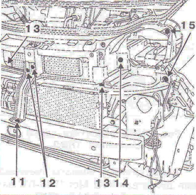
Figure 3.88. Unscrew bolts 11-15 and remove the upper cross beam.

Figure 3.88. Unscrew bolts 11-15 and remove the upper cross beam.


10. Disconnect the wiring connectors from the fuel pressure regulator 1, pressure sensor 2, fuel temperature sensor 3 (figure 3.89).
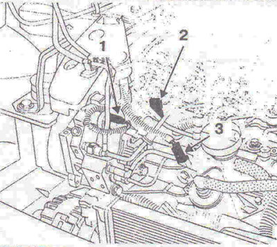
Figure 3.89. Disconnect the wiring connectors from the fuel pressure regulator 1, pressure sensor…

Figure 3.89. Disconnect the wiring connectors from the fuel pressure regulator 1, pressure sensor 2, fuel temperature sensor 3.


11. Disconnect the pressure and drain fuel lines and plug the holes with plugs (figure 3.90).
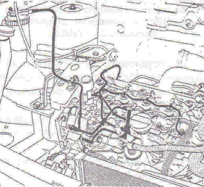
Figure 3.90. Disconnect the pressure and drain fuel lines and plug the holes with plugs.

Figure 3.90. Disconnect the pressure and drain fuel lines and plug the holes with plugs.


12. Disconnect the high pressure fuel lines using tool Mot. 1383, then plug the holes with plugs (figure 3.91).
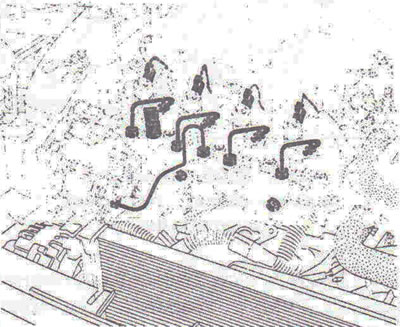
Figure 3.91. Disconnect the high pressure fuel lines using tool Mot. 1383, then plug the holes with…

Figure 3.91. Disconnect the high pressure fuel lines using tool Mot. 1383, then plug the holes with plugs.


13. Unscrew bolts 4 securing the high-pressure accumulator, remove the high-pressure accumulator, unscrew bolts 5 securing the rear bracket of the high-pressure fuel pump and remove the rear bracket of the high-pressure fuel pump (figure 3.92).
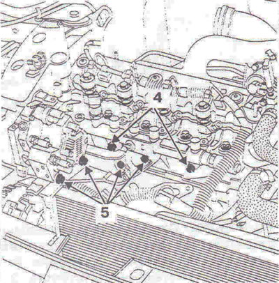
Figure 3.92. Unscrew bolts 4 securing the high-pressure accumulator, remove the high-pressure…

Figure 3.92. Unscrew bolts 4 securing the high-pressure accumulator, remove the high-pressure accumulator, unscrew bolts 5 securing the rear bracket of the high-pressure fuel pump and remove the rear bracket of the high-pressure fuel pump.


14. Set the crankshaft to the TDC position of the piston of the 1st cylinder and lock the shaft with the locking tool Mot. 1054.

15. Install engine support devices Mot. 1367 and Mot. 1367-02.

16. Remove the engine pendulum mount (figure 3.93).
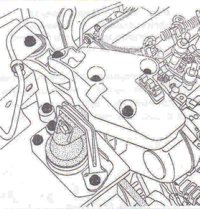
Figure 3.93. Remove the engine pendulum mount.

Figure 3.93. Remove the engine pendulum mount.


17. Unscrew the bolts 1 securing the timing belt cover and remove it (figure 3.94).

18. Fit the pulley locking device Mot. 1200-02 to the pulley.

19. Unscrew nut 2 securing the fuel injection pump pulley (figure 3.95).
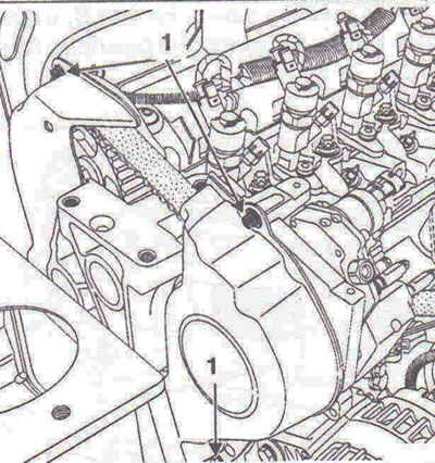
Figure 3.94. Unscrew bolts 1 securing the timing belt cover and remove it.
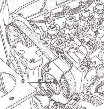
Figure 3.94. Unscrew bolts 1 securing the timing belt cover and remove it.


Figure 3.95. Unscrew nut 2 securing the fuel injection pump pulley.

Figure 3.95. Unscrew nut 2 securing the fuel injection pump pulley.


20. Unscrew the 3 fuel injection pump mounting nuts (figure 3.96).
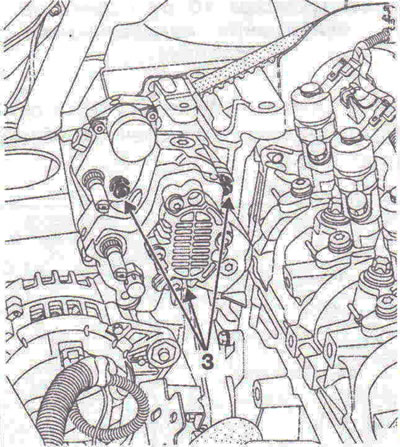
Figure 3.96. Unscrew nuts 3 securing the high-pressure fuel pump.

Figure 3.96. Unscrew nuts 3 securing the high-pressure fuel pump.


21. Fit the jaws of the F9Q engine puller Mot. 1525-01, then the pulley puller Mot. 1525.

22. Remove the fuel injection pump by tightening the pressure bolt 4 of the pulley puller (figure 3.97).
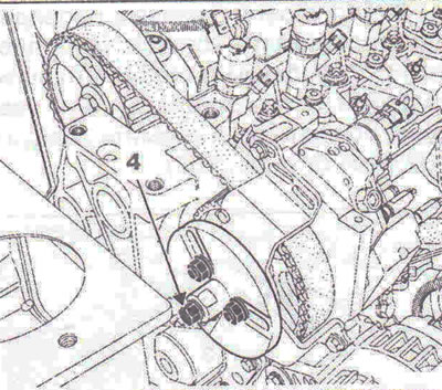
Figure 3.97. Remove the fuel injection pump by tightening the pressure bolt 4 of the pulley puller.

Figure 3.97. Remove the fuel injection pump by tightening the pressure bolt 4 of the pulley puller.


Installation


23. For any operation, remove the protective plugs immediately before installing the part in place.

24. Installation is carried out in the reverse order of removal.

Installing the rear fuel injection pump bracket


25. Install the rear pump bracket and hand tighten the mounting bolts until the bracket contacts the pump and cylinder head.


26. Tighten the rear bracket mounting bolts to a torque of 30 Nm, first tightening bolts 1 on the pump, then bolts 2 on the cylinder head (figure 3.98).
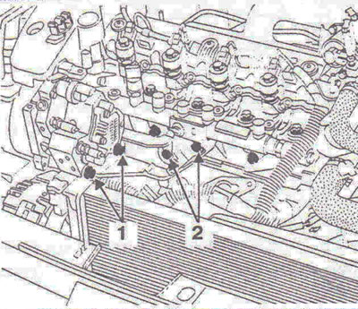
Figure 3.98. Tighten the rear bracket mounting bolts to a torque of 30 Nm, first tightening bolts 1…

Figure 3.98. Tighten the rear bracket mounting bolts to a torque of 30 Nm, first tightening bolts 1 on the pump, then bolts 2 on the cylinder head.


Installation of high pressure accumulator and high pressure fuel lines


27. Install the high pressure accumulator in place and tighten the mounting bolts by hand, without tightening them completely (the accumulator should be in the "floating" position).

28. Install the high pressure fuel lines by hand tightening the nuts on the pump and injector side, then on the accumulator side.

29. Tighten the battery mounting bolts 3 to 22 Nm (figure 3.99).
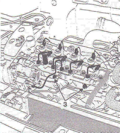
Figure 3.99. Tighten the battery mounting bolts 3 to a torque of 22 Nm.

Figure 3.99. Tighten the battery mounting bolts 3 to a torque of 22 Nm.


30. Tighten the high-pressure fuel lines to 25 Nm, first tightening the nuts on the pump and injector side, then on the battery side

31. Each time the high-pressure fuel pump is removed, the fuel drain line 4 must be replaced (figure 3.100).
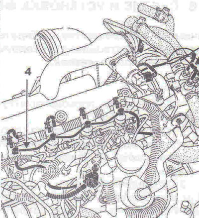
Figure 3.100. Each time the high-pressure fuel pump is removed, the fuel drain line 4 must be…

Figure 3.100. Each time the high-pressure fuel pump is removed, the fuel drain line 4 must be replaced.


Tightening torques


  • High pressure fuel line fastening nuts - 25±2 Nm.
  • Fuel injection pump mounting bolts - 30±3 Nm.
  • Fuel injection pump rear bracket mounting bolt - 30±3 Nm.
  • Fuel injection pump pulley mounting nut - 15 Nm, then tighten further by 60±10°.
  • High pressure accumulator mounting bolts - 22±2 Nm.


This article is available at russian, bulgarian, belarusian, ukrainian, serbian, croatian, romanian, polish, slovak, hungarian
Checking the article: Meshcheryakov Damir

Share information:

Previous articles
Opel Vivaro A: Diesel engine F9Q
Next articles

Removal and installation the fuel filter
Removal and installation the fuel pump
Technical characteristics of fuel injection system components
Fuel injection system
Removal and installation the charge air cooling radiator (intercooler)
Removal and installation a turbocharger
Removal and installation a high pressure accumulator
Removal and installation injectors
Removal and installation the fuel pressure sensor
Removal and installation the accelerator pedal position sensor
Centralized coolant temperature control
Removal and installation the fuel injection system control unit


See similar ones from other Opel car manuals:
▶ Checking and adjusting the moment of start of injection of… Opel Kadett D (1979-1984)
▶ Moment of injection start of the high-pressure fuel pump —… Opel Omega A (1986-1993)
▶ High pressure fuel pump — removal and installation Opel Vectra B (1995-2002)
▶ Replacing the high pressure fuel line Opel Corsa C (2000-2006, petrol)
▶ Fuel pump — checking, removal, installation Opel Astra F (1991-1998, petrol)
Link to this page in different formats

Visitor comments


No comments yet


How much will 40 + 23 =


Vivaro A (2001-2014) 
  • General information
  • User manual
  • Power unit
  • Petrol engine F4R
  • Diesel engine F9Q
  • Diesel engine G9U
  • Transmission
  • Clutch and drive shafts
  • Manual gearbox
  • Chassis
  • Front suspension
  • Rear suspension
  • Brake system
  • Body
  • Exterior
  • Interior
  • Electrical equipment
  • Heating and ventilation
  • Air conditioner
  • Equipment and devices
  • Electrical diagrams
Ascona C (1981-1988) 
  • General information
  • Maintenance
  • Power unit
  • Gasoline engines
  • Diesel engines
  • Cooling system
  • Fuel and exhaust system
  • Contact ignition system
  • Contactless ignition system
  • Transmission
  • Clutch
  • Mechanical gearbox
  • Automatic gearbox
  • Drive shafts
  • Chassis
  • Steering
  • Brake system
  • Car suspension
  • Body
  • Exterior
  • Interior
  • Doors and windows
  • Electrical equipment
  • Equipment and devices
  • Power devices
  • Electrical circuits
Frontera B (1998-2004) 
  • General information
  • User manual
  • Maintenance
  • Power unit
  • Petrol engines 2.2 l
  • Petrol engines 3.2 l
  • Diesel engines 2.2 l
  • Cooling system
  • Fuel system (petrol)
  • Fuel system (diesel)
  • Ignition system
  • Transmission
  • Clutch
  • Manual gearbox MUA5C
  • Automatic gearbox 4L30E
  • Chassis
  • Suspension and axles
  • Steering
  • Brake system
  • Body
  • Exterior
  • Interior
  • Doors, locks and windows
  • Heating and air conditioning
  • Electrical equipment
  • Power devices
  • Equipment and devices
  • Lighting and signaling
  • Electrical diagrams
Frontera A (1991-1998, petrol) 
  • General information
  • Introduction to guide
  • User manual
  • Maintenance
  • Power unit
  • Engine repair
  • Lubrication system
  • Cooling system
  • Power and exhaust system
  • Engine electrics
  • Transmission
  • Clutch
  • Mechanical gearbox
  • Cardan shafts
  • Chassis
  • Brake system
  • Front suspension
  • Rear suspension
  • Steering
  • Body
  • Repair and care
  • Electrical equipment
  • Equipment and devices
  • Electrical circuits
OpelBook.ru © 2017–2026 · Mobile version · · Sitemap: EN BG BY UA RS HR RO PL SK HU · Feedback · Site search
Astra F, petrol · Astra G, petrol · Astra G · Astra H · Astra J, petrol · Corsa B · Corsa C, petrol · Corsa C · Insignia A · Kadett D · Kadett E · Omega A · Omega B · Omega B2 · Vectra A, petrol · Vectra A · Vectra B, petrol · Vectra B · Vectra C · Zafira A, petrol · Frontera A, petrol · Frontera B · Ascona C · Vivaro A ·
We want your visit to be comfortable 🤝! We use cookies 🍪 to make that happen.