
OpelBook.ru
Cars AvtoVAZ Cars Mitsubishi Cars BMW Cars Mercedes Cars Nissan Cars Toyota Cars Chevrolet
English Русский
Български
Беларускі
Український
Српски
Hrvatski
Română
Polski
Slovenský
Magyar
 |  Sitemap  |  Contacts  |    


Main Astra Corsa Insignia Kadett Omega Vectra Zafira Others Articles
Frontera A (1991-1998, petrol) Frontera B (1998-2004) Ascona C (1981-1988) Vivaro A (2001-2014)
  • Main
  • Opel
  • Vivaro A
  • Power unit
  • Diesel engine F9Q
  • Fuel injection system

Fuel injection system (Opel Vivaro A)

            0

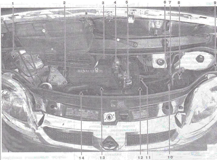
The location of the injection system elements in the engine compartment is shown in the figure 3.64-3.73.

Figure 3.64. Location of injection system elements in the engine compartment: 1 - Fuel filter with…

Figure 3.64. Location of injection system elements in the engine compartment: 1 - Fuel filter with heater; 2 - Camshaft position sensor; 3 - Air flow meter with built-in air temperature sensor; 4 - Exhaust gas recirculation solenoid valve; 5 - Immersion heater housing; 6 - Boost pressure control solenoid valve; 7 - Boost pressure sensor; 8 - Fuel injection control unit; 9 - Fuel cut-off inertia switch; 10 - Pre- and post-heating unit; 11 - Coolant temperature sensor; 12 - Crankshaft speed sensor; 13 - Electromagnetic injector;14 - Fuel injection pump.
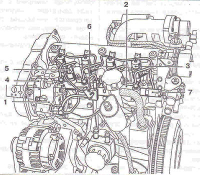

Figure 3.65. Location of injection system elements in the engine compartment: 1 - Fuel injection…

Figure 3.65. Location of injection system elements in the engine compartment: 1 - Fuel injection pump; 2 - High pressure accumulator; 3 - Nozzle; 4 - Fuel pressure regulator; 5 - Fuel pressure sensor; 6 - Fuel temperature sensor; 7 - Pressure regulator.
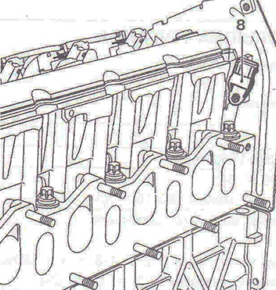


Figure 3.66. Location of injection system elements in the engine compartment: 8 - Camshaft position…

Figure 3.66. Location of injection system elements in the engine compartment: 8 - Camshaft position sensor.


Source is on this resource (www.OPELBOOK.ru)
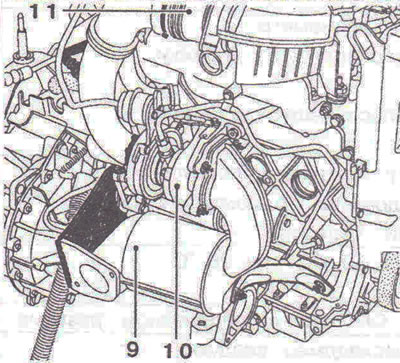
Figure 3.67. Location of injection system elements in the engine compartment: 9 - Catalyst; 10 -…

Figure 3.67. Location of injection system elements in the engine compartment: 9 - Catalyst; 10 - Turbocharger; 11 - Air flow meter with built-in air temperature sensor.
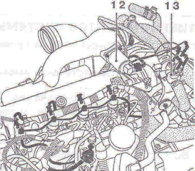

Figure 3.68. Location of injection system elements in the engine compartment: 12 - Exhaust gas…

Figure 3.68. Location of injection system elements in the engine compartment: 12 - Exhaust gas recirculation solenoid valve; 13 - Immersion heater housing.
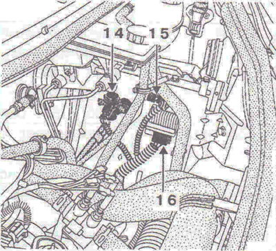


Figure 3.69. Location of injection system elements in the engine compartment: 14 - Boost pressure…

Figure 3.69. Location of injection system elements in the engine compartment: 14 - Boost pressure control solenoid valve; 15 - Boost pressure sensor; 16 - Pre- and post-heating unit.
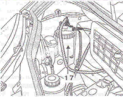

Figure 3.70. Location of injection system elements in the engine compartment: 17 - Fuel filter.
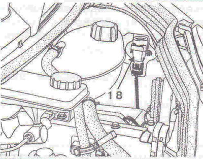
Figure 3.70. Location of injection system elements in the engine compartment: 17 - Fuel filter.


Figure 3.71. Location of injection system elements in the engine compartment: 18 - Fuel supply…

Figure 3.71. Location of injection system elements in the engine compartment: 18 - Fuel supply cut-off inertia switch.
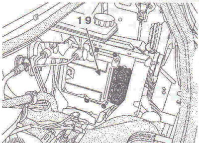


Figure 3.72. Location of injection system elements in the engine compartment: 19 - Fuel injection…

Figure 3.72. Location of injection system elements in the engine compartment: 19 - Fuel injection control unit.
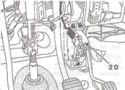

Figure 3.73. Location of injection system elements in the engine compartment: 20 - Fuel pedal…

Figure 3.73. Location of injection system elements in the engine compartment: 20 - Fuel pedal position sensor.


Vehicles equipped with diesel engines with a high-pressure CDI injection system are provided with two injection system warning lights. These warning lights come on during the "pre-heating" phase and in the event of faults in the injection system.

When the key in the instrument and starter switch is set to position "M", the indicator light comes on during the "pre-heating" phase and then goes out.

In case of a malfunction of the injection system (severity level 1) the "engine fault" indicator light and the preheating indicator light come on and remain on continuously, indicating that you need to contact a Renault service centre.


Such faults include:
  • fuel injection system control unit malfunction;
  • malfunction of the electronic engine start interlock system;
  • no engine crankshaft speed signal (the engine does not start);
  • fuel pedal position sensor malfunction;
  • mass fuel flow sensor malfunction;
  • vehicle speed sensor malfunction;
  • exhaust gas recirculation solenoid valve malfunction;
  • malfunction of the boost pressure control solenoid valve;
  • boost pressure sensor malfunction;
  • misalignment of signals from the top dead center position sensor and the camshaft position sensor.

In case of serious malfunction of the injection system (severity level 2) the warning light with the engine symbol and the word "STOP" will flash and the vehicle must be stopped immediately.

Such faults include:
  • fuel injection system control unit malfunction;
  • injector malfunction;
  • deviation from the norm of the supply voltage of the injection system control unit;
  • high pressure accumulator pressure sensor malfunction;
  • high pressure accumulator pressure regulator malfunction;
  • misalignment of signals from the top dead center position sensor and the camshaft position sensor.

If the engine overheats, the warning light with the engine symbol and the word "STOP" lights up continuously.


This article is available at russian, bulgarian, belarusian, ukrainian, serbian, croatian, romanian, polish, slovak, hungarian
Checking the article: Meshcheryakov Damir

Share information:

Previous articles
Opel Vivaro A: Diesel engine F9Q
Next articles

Removal and installation the charge air cooling radiator (intercooler)
Removal and installation a turbocharger
Boost pressure adjustment
Boost pressure control valve
Removal and installation the air flow meter
Removal and installation of collectors
Technical characteristics of fuel injection system components
Removal and installation the fuel pump
Removal and installation the fuel filter
Removal and installation the high pressure fuel pump
Removal and installation a high pressure accumulator
Removal and installation injectors


See similar ones from other Opel car manuals:
▶ Multec Single Point Fuel Injection System Components —… Opel Astra F (1991-1998, petrol)
▶ General information about the fuel injection system of a… Opel Corsa B (1993-2000)
▶ Checking and adjusting the GM «Multec SPI» fuel injection… Opel Kadett E (1984-1995)
▶ Fuel injection system — precautions Opel Omega A (1986-1993)
▶ General description of the injection fuel system Opel Vectra A (1988-1995, petrol)
Link to this page in different formats

Visitor comments


No comments yet


How much will 44 + 42 =


Vivaro A (2001-2014) 
  • General information
  • User manual
  • Power unit
  • Petrol engine F4R
  • Diesel engine F9Q
  • Diesel engine G9U
  • Transmission
  • Clutch and drive shafts
  • Manual gearbox
  • Chassis
  • Front suspension
  • Rear suspension
  • Brake system
  • Body
  • Exterior
  • Interior
  • Electrical equipment
  • Heating and ventilation
  • Air conditioner
  • Equipment and devices
  • Electrical diagrams
Ascona C (1981-1988) 
  • General information
  • Maintenance
  • Power unit
  • Gasoline engines
  • Diesel engines
  • Cooling system
  • Fuel and exhaust system
  • Contact ignition system
  • Contactless ignition system
  • Transmission
  • Clutch
  • Mechanical gearbox
  • Automatic gearbox
  • Drive shafts
  • Chassis
  • Steering
  • Brake system
  • Car suspension
  • Body
  • Exterior
  • Interior
  • Doors and windows
  • Electrical equipment
  • Equipment and devices
  • Power devices
  • Electrical circuits
Frontera B (1998-2004) 
  • General information
  • User manual
  • Maintenance
  • Power unit
  • Petrol engines 2.2 l
  • Petrol engines 3.2 l
  • Diesel engines 2.2 l
  • Cooling system
  • Fuel system (petrol)
  • Fuel system (diesel)
  • Ignition system
  • Transmission
  • Clutch
  • Manual gearbox MUA5C
  • Automatic gearbox 4L30E
  • Chassis
  • Suspension and axles
  • Steering
  • Brake system
  • Body
  • Exterior
  • Interior
  • Doors, locks and windows
  • Heating and air conditioning
  • Electrical equipment
  • Power devices
  • Equipment and devices
  • Lighting and signaling
  • Electrical diagrams
Frontera A (1991-1998, petrol) 
  • General information
  • Introduction to guide
  • User manual
  • Maintenance
  • Power unit
  • Engine repair
  • Lubrication system
  • Cooling system
  • Power and exhaust system
  • Engine electrics
  • Transmission
  • Clutch
  • Mechanical gearbox
  • Cardan shafts
  • Chassis
  • Brake system
  • Front suspension
  • Rear suspension
  • Steering
  • Body
  • Repair and care
  • Electrical equipment
  • Equipment and devices
  • Electrical circuits
OpelBook.ru © 2017–2026 · Mobile version · · Sitemap: EN BG BY UA RS HR RO PL SK HU · Feedback · Site search
Astra F, petrol · Astra G, petrol · Astra G · Astra H · Astra J, petrol · Corsa B · Corsa C, petrol · Corsa C · Insignia A · Kadett D · Kadett E · Omega A · Omega B · Omega B2 · Vectra A, petrol · Vectra A · Vectra B, petrol · Vectra B · Vectra C · Zafira A, petrol · Frontera A, petrol · Frontera B · Ascona C · Vivaro A ·
We want your visit to be comfortable 🤝! We use cookies 🍪 to make that happen.