


Contents: Removal ⬇ Installation ⬇
Removal
1. Disconnect the battery.
2. Disconnect the wiring connector 1 from the heater (figure 3.47). Unscrew the three bolts and three nuts 2 securing the heater and remove it.
3. Disconnect wiring connector 3 from the air flow meter and air duct 4 from the turbocharger (figure 3.52). Unscrew the bolts 5 securing the air filter housing, then remove the air filter housing.
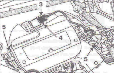
Figure 3.52. Disconnect wiring connector 3 from the air flow meter and air duct 4 from the turbocharger. Unscrew the bolts 5 securing the air filter housing.
4. Unscrew the two bolts 6 securing the air flow meter to the air filter housing and remove the air flow meter (figure 3.53).
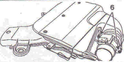
Figure 3.53. Unscrew the two bolts 6 securing the air flow meter to the air filter housing and remove the air flow meter.
Installation
5. Installation is carried out in the reverse order of removal.
Assigning contacts
Air flow meter connector with integrated air temperature sensor (figure 3.54).
Air temperature sensor resistance: when measured between contacts 1 and 2: 2170 Ohm at 20°C.
- Contact 1 - Air temperature.
- Contact 2 - Ground connection.
- Contact 3 - 5V, control voltage.
- Contact 4 - "+" of the battery.
- Contact 5 - Air flow meter signal.
- Contact 6 - Ground connection.
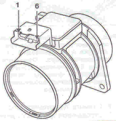
Figure 3.54. Purpose of air flow meter contacts.
Visitor comments