


Contents: Removal ⬇ Installation ⬇
Removal
1. Place the vehicle on a four-post lift.
2. Disconnect the battery. The battery is located under the left seat, so you need to remove the floor mat by detaching the clips holding it, then the battery cover A by unscrewing the bolts (figure 3.22).
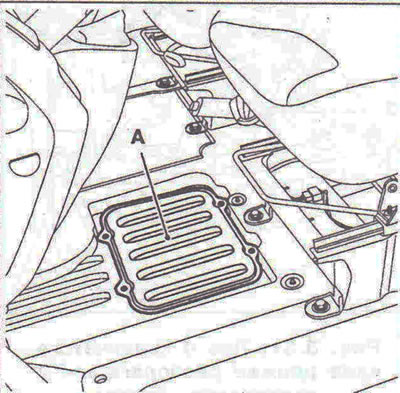
Figure 3.22. The battery is located under the left seat, so you need to remove the floor mat by detaching the latches holding it, then the battery cover A by unscrewing the bolts.
3. Remove the engine sump guard and left side guard.
4. Fit engine support Mot. 136702 between the lower cross member and the subframe (figure 3.23).
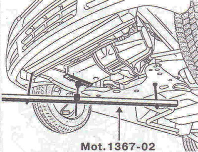
Figure 3.23. Fit engine support Mot. 1367-02 between the lower cross member and the subframe.
5. Position the upper part A of the tool so that it contacts the engine oil pan. Adjust the position of part A in relation to the engine oil pan using fasteners B. Raise the engine slightly at point C, then tighten nuts D (figure 3.24).
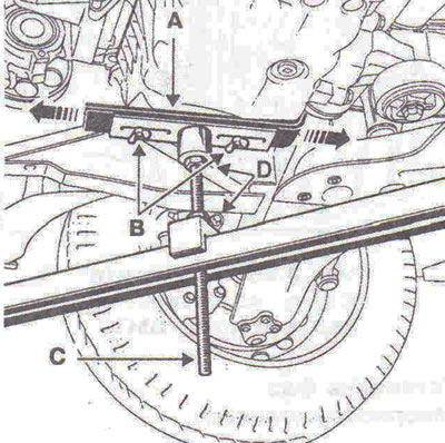
Figure 3.24. Position the upper part A of the tool so that it contacts the engine oil pan. Adjust the position of part A in relation to the engine oil pan using fasteners B. Raise the engine slightly at point C, then tighten nuts D.
6. Disconnect the wiring harness from the engine mount and move it to the side. Disconnect the power steering fluid reservoir from the bracket and set it aside.
7. Remove the accessory drive belt.
8. Unscrew the bolts securing the rod 1, then remove the "pendulum suspension support - travel limiter" unit (figure 3.25).
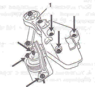
Figure 3.25. Unscrew the bolts securing rod 1, then remove the "pendulum suspension support - travel limiter" unit.
9. Unscrew the plug from the hole for the TDC lock (figure 3.26).
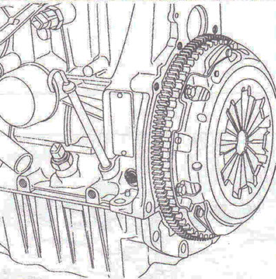
Figure 3.26. Unscrew the plug from the hole for the TDC lock.
Setting the valve timing
10. Rotate the crankshaft clockwise (if you look from the timing belt side), as soon as mark 1 on the camshaft toothed pulley appears in window 2 of the timing belt cover, press the TDC lock Mot. 1054 until the crankshaft is locked (the mark on the camshaft toothed pulley should be located almost in the center of the window) (figure 3.27).
11. Remove the accessory drive belt tensioner 3, the crankshaft pulley, blocking the flywheel, the timing belt cover, acting from below the vehicle (lower the engine using the engine support bar Mot.1453) (figure 3.28).
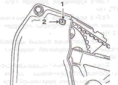
Figure 3.27. Rotate the crankshaft clockwise (if you look from the timing belt side), as soon as mark 1 on the camshaft toothed pulley appears in window 2 of the timing belt cover, press the TDC lock Mot. 1054 until the crankshaft is locked.
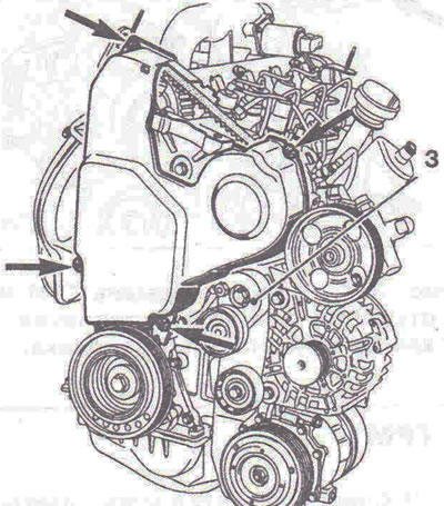
Figure 3.28. Remove the auxiliary equipment drive belt tensioner 3, the crankshaft pulley, blocking the flywheel, and the timing belt cover.
12. Loosen the tension roller by loosening nut 5, then remove the timing belt (figure 3.29).
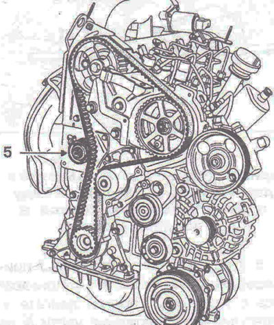
Figure 3.29. Loosen the tension roller by loosening nut 5, then remove the timing belt.
Installation
Tension
13. Install the timing belt on a cold engine (after the engine has cooled down to outside air temperature).
14. Make sure that the tension roller is correctly installed on pin 1 (figure 3.30).
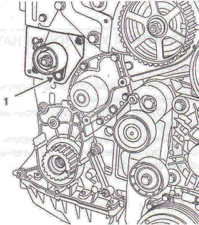
Figure 3.30. Make sure that the tension roller is correctly installed on pin 1.
15. Make sure that the TDC locking tool Mot. 1054 is installed. Groove 4 of the crankshaft should be located 2 in the middle between the two ribs of the front cover of the cylinder block, while mark 3 on the toothed pulley of the crankshaft should be shifted by one tooth to the left of the vertical axis of the engine (figure 3.31).
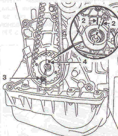
Figure 3.31. Groove 4 of the crankshaft should be located 2 in the middle between the two ribs of the front cover of the cylinder block, while mark 3 on the toothed pulley of the crankshaft should be shifted by one tooth to the left of the vertical axis of the engine.
16. Place the new timing belt on the pulleys, aligning the marks on the belt with the marks on the toothed pulleys of the camshaft and crankshaft. Press the tension roller to the belt by screwing in bolt 2 on the tension roller bracket (figure 3.32).
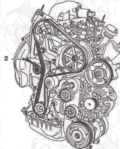
Figure 3.32. Press the tension roller to the belt by screwing in bolt 2 on the tension roller bracket.
17. Remove TDC locking tool Mot. 1054. Install the crankshaft pulley mounting bolt with washer R1 4, included in tool Mot. 1543 (figure 3.33a, b). Be sure to remove the washer when installing the crankshaft pulley.
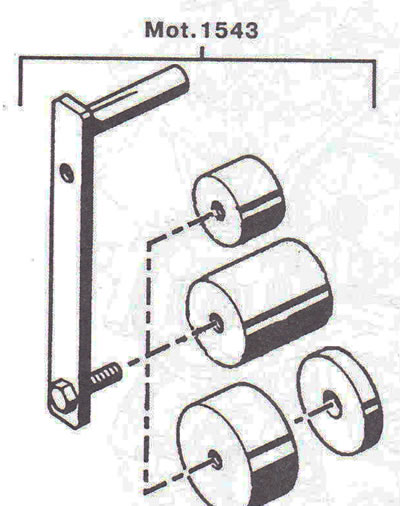
Figure 3.33b. Device Mot. 1543.
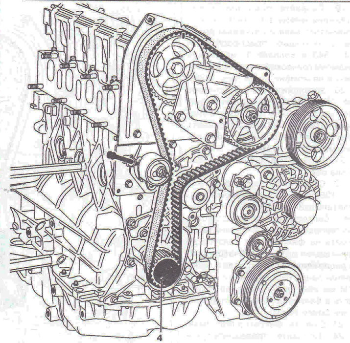
Figure 3.33a. Install the crankshaft pulley mounting bolt with the R1 4 washer included in the Mot. 1543 tool kit.
18. Fit tool Mot. 1543 and cap 1 onto the crankshaft pulley mounting bolt (figure 3.34).
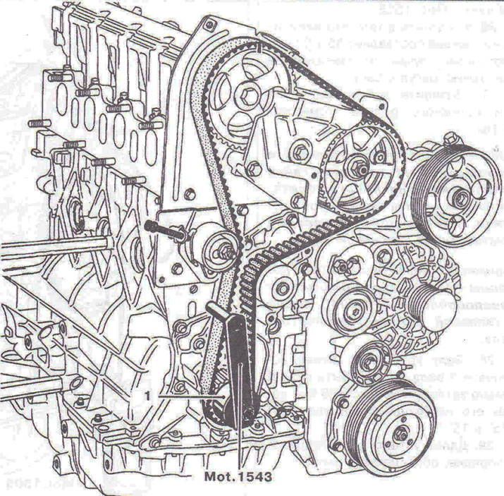
Figure 3.34. Fit tool Mot. 1543 and cap 1 onto the crankshaft pulley mounting bolt.
19. Create a pre-tension between the crankshaft sprocket and the tension roller using tool Mot. 1543 and cap 1, using a torque wrench set to 11 Nm (figure 3.35).
20. Install the sensor of the Mot. 1505 device. Using bolt 2, tighten the belt until the required tension value of 88±3 Hz is obtained. Tighten the tension roller axle mounting nut to a torque of 10 Nm (figure 3.36).
21. Rotate the crankshaft two revolutions.
22. Reinstall the Mot. 1054 locking tool and set the valve timing mechanism to the position corresponding to the valve timing setting(start pressing the locking pin half a tooth before the mark on the camshaft toothed pulley aligns with the mark previously applied on the inner timing belt casing, so as not to accidentally hit the crankshaft balancing hole).
23. Remove the retainer Mot. 1054.
24. Create a pre-tension between the crankshaft toothed pulley and the tension roller using tool Mot. 1543 and cap 1, using a torque wrench set to 11 Nm.
25. Install the sensor of the Mot. 1505 device.
26. Make sure that the tension value is 85±3Hz, otherwise, readjust it.
27. Tighten the tension roller axle mounting nut to a torque of 50 Nm.
Note: Strictly adhere to the specified tightening torque of the tension roller axle nut to prevent loosening, which may cause engine damage.
Caution: Remove washer number R1, included in tool Mot. 1543, before installing the crankshaft pulley.
28. The crankshaft pulley mounting bolt must be tightened to a torque of 20 Nm, then it must be turned further by 115° ±15°.
29. Further installation is carried out in the reverse order of removal.
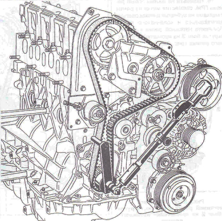
Figure 3.35. Create a pre-tension between the crankshaft toothed pulley and the tension roller using tool Mot. 1543 and cap 1, using a torque wrench.
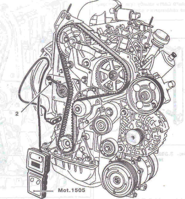
Figure 3.36. Install the sensor of the Mot. 1505 instrument. Using bolt 2, tighten the belt until the required tension value is obtained.
Visitor comments