


Contents: Removal ⬇ Installation ⬇
Removal
1. Place the vehicle on a four-post lift.
2. Disconnect the battery. The battery is located under the left seat, so you need to remove the floor mat by detaching the latches holding it, then the battery cover A by unscrewing the bolts that secure it (figure 3.1).
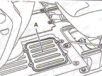
Figure 3.1. Location of the battery.
3. Remove the wiring on the battery, front wheels, engine sump guard, ground wire to the body and move the battery wiring harness to the side.
4. Remove the lower noise insulation of the gearbox at points 1 (figure 3.2).
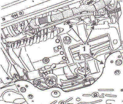
Figure 3.2. Remove the lower noise insulation of the gearbox at points 1.
5. Drain the refrigerant from the air conditioner refrigeration circuit using a charging station, the coolant by disconnecting the pipe from the radiator, the oil from the gearbox and engine, if necessary.
On the right side of the car
6. Remove the floating brake caliper and hang it on the suspension spring, ABS sensor, unscrew the suspension arm ball joint mounting nut (use a hex key cut to size X = 22 mm if necessary to lock the ball joint) (figure 3.3).
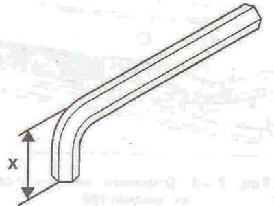
Figure 3.3. Loosen the suspension arm ball joint mounting nut (use a hex key cut to size X = 22 mm if necessary to lock the ball joint).
7. Unscrew the two bolts securing the axle shaft flange to the intermediate support, remove the steering rod ball joint using the T.Av.476 tool, and unscrew the bolts securing the shock absorber strut to the steering knuckle.
8. Disconnect the axle shaft, then remove the hub assembly with the axle shaft.
On the left side of the car
9. Remove the floating brake caliper and hang it on the suspension spring, ABS sensor, unscrew the suspension arm ball joint mounting nut (use a hex key cut to size X = 22 mm if necessary to lock the ball joint) (figure 3.3).
10. Remove the steering rod ball joint using the T.Av.476 tool.
11. Unscrew the bolts securing the inner axle joint boot holder and the bolts securing the shock absorber strut to the steering knuckle.
12. Disconnect the axle shaft, then remove the hub assembly with the axle shaft.
13. Remove the front license plate and radiator grille (figure 3.4).
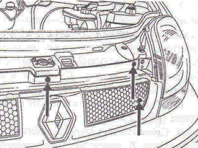
Figure 3.4. Remove the radiator grille.
14. Unscrew the 2 headlight mounting bolts (figure 3.5).
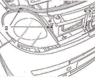
Figure 3.5. Unscrew the bolts 2 securing the headlights.
15. Disconnect the wiring connectors from the headlights.
16. Remove the headlights by disconnecting the clips 3 (figure 3.6).
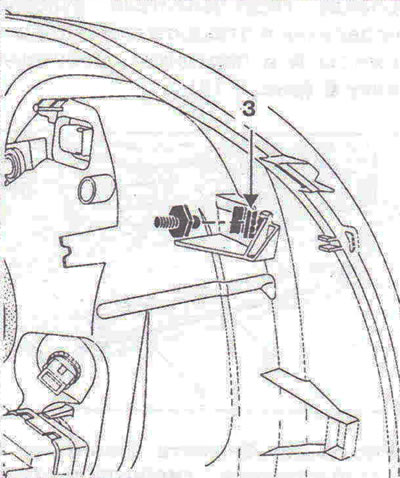
Figure 3.6. Remove the headlights by detaching the clips 3.
17. Remove the bumper (figure 3.7a, b).
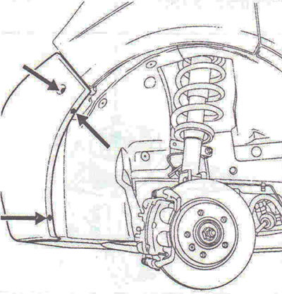
Figure 3.7a. Remove the bumper.
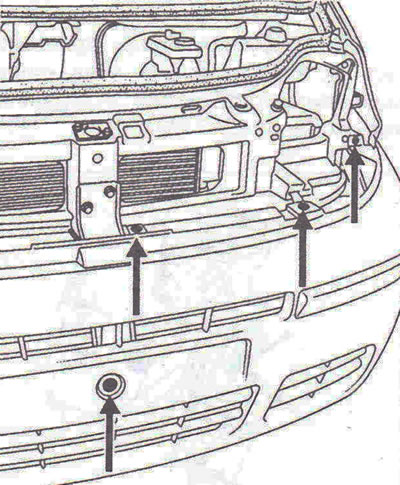
Figure 3.7b. Remove the bumper.
18. Remove the power steering fluid reservoir from the bracket.
19. Disconnect the air ducts from the intermediate air cooling radiator, as well as the fastener 4 (figure 3.8).
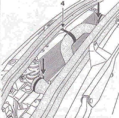
Figure 3.8. Disconnect the air ducts from the intermediate air cooling radiator, as well as the fastener 4.
20. Disconnect the 5 fasteners of the hood lock drive cable and remove the cable, remove the front body panel (figure 3.9).
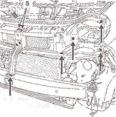
Figure 3.9. Disconnect the 5 fasteners of the hood lock drive cable and remove the cable, remove the front body panel.
21. Unscrew the radiator mounting bolts from below and disconnect the supply pipe.
22. Disconnect the wiring connectors from the cooling fan and condenser.
23. Disconnect the air conditioner pipe fastenings to the compressor and condenser.
24. Remove the radiator of the cooling system together with the condenser, disconnect the air intake pipe from the air filter housing, fastening 1 of the pre-heating and post-heating unit, electromagnetic valve of the boost pressure regulation 2, boost pressure sensor 3, wiring connectors from the knock sensor 6, the expansion tank and move it to the side, protective casing A of the fuel injection control unit (figure 3.10).
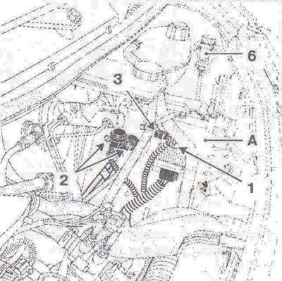
Figure 3.10. Remove the fastening 1 of the pre-heating and post-heating unit, the boost pressure control electromagnetic valve 2, the boost pressure sensor 3, the wiring connectors from the knock sensor 6, the expansion tank and move it to the side, the protective cover A of the fuel injection control unit.
25. Disconnect the wiring connectors 5 and release the fuse holder 6 from the latches (figure 3.11).
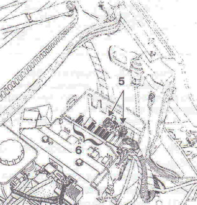
Figure 3.11. Disconnect wiring connectors 5 and release fuse holder 6 from the latches.
26. Unscrew the bolt securing the ground wire to the gearbox, as well as the bolt securing it to the left side member, then move the switching unit assembly to the side.
27. Disconnect the heater hoses in the engine compartment bulkhead area, the brake booster vacuum tube, and the fuel supply line 7 (install protective plugs), and also wiring connector 8 (figure 3.12).
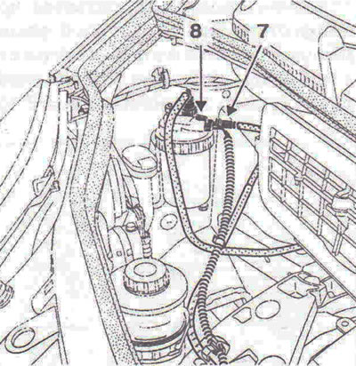
Figure 3.12. Disconnect the fuel supply line 7 (install protective plugs), and also wiring connector 8.
28. Unscrew the mounting bolt 9, disconnect the clutch slave cylinder pipeline by removing the latch B, and move it to the side (figure 3.13).
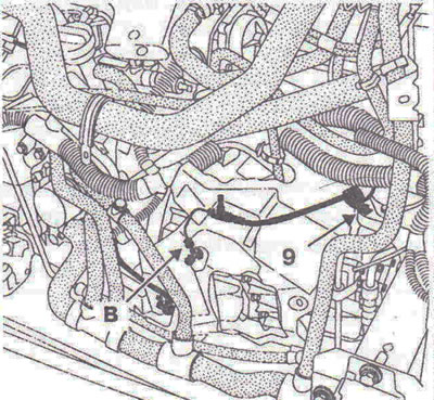
Figure 3.13. Unscrew the mounting bolt 9, disconnect the clutch slave cylinder line by removing the latch B, and move it to the side.
29. Remove the gearbox sound insulation.
30. Disconnect the gear selector and shift cables.
31. Remove the heater radiator C by disconnecting the wiring connector 1 (figure 3.14).
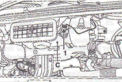
Figure 3.14. Remove heater radiator C by disconnecting wiring connector 1.
32. Unscrew bolt 2 securing the immersion heater housing and move it to the side (figure 3.15).
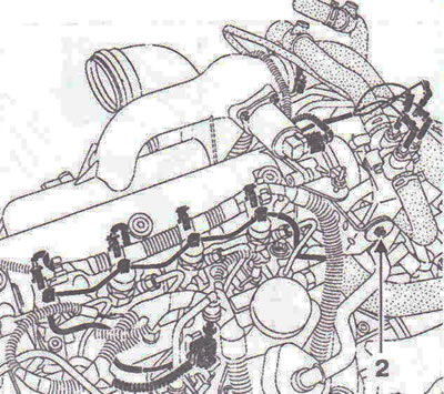
Figure 3.15. Unscrew bolt 2 securing the immersion heater housing and move it to the side.
33. Disconnect the power steering pipes from the steering gear, after removing the oil from the power steering pump reservoir.
34. Unscrew bolt 3 and loosen bolt 4 (figure 3.16).
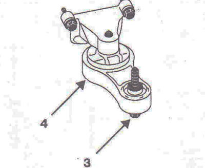
Figure 3.16. Unscrew bolt 3 and loosen bolt 4.
35. Disconnect the exhaust system inlet pipe fastening.
36. Disconnect the fuel level sensor connector at point 5, disconnect it from the underbody and secure it to the engine (figure 3.17).
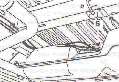
Figure 3.17. Disconnect the fuel level sensor connector at point 5, disconnect it from the bottom of the body and secure it to the engine.
37. Install the shop crane.
38. Raise the engine and gearbox assembly using a lifting chain.
39. Remove the 7 fastening of the power steering pipe and move it to the side, the lower A and the front cross member B (figure 3.18).
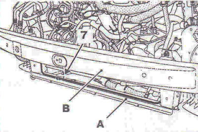
Figure 3.18. Remove the fastening 7 of the power steering pipe and move it to the side, the lower A and the front cross member B.
40. Unscrew nut 1 and use a punch to knock out the mounting stud (figure 3.19).
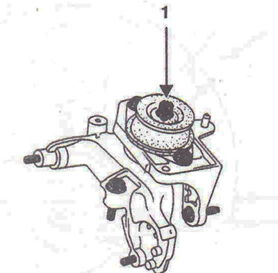
Figure 3.19. Unscrew nut 1 and use a punch to knock out the mounting stud.
41. Unscrew the tie rod mounting bolts 2, then remove the "pendulum suspension support - travel limiter" unit (figure 3.20).
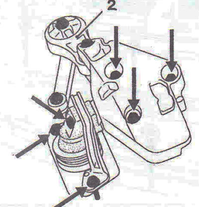
Figure 3.20. Unscrew the bolts securing rod 2, then remove the "pendulum suspension support - travel limiter" unit.
42. Using a shop crane, remove the engine assembly with the gearbox.
Installation
43. Installation is carried out in the reverse order of removal.
Tightening torques
- Nuts for the bolts securing the shock absorber strut to the steering knuckle - 180 Nm.
- Steering rod mounting nut -370 Nm.
- Gearbox pendulum support mounting nut - 62 Nm.
- Front suspension arm ball joint pin mounting nut -110 Nm.
- Brake mechanism floating caliper mounting bolts - 35 Nm.
- Reactive thrust mounting bolt - 105 Nm.
- Upper pendulum suspension link mounting bolt - 105 Nm.
- Bolts for fastening the holder of the inner joint boot of the left half-axle - 30 Nm.
- The bolt for fastening the pendulum suspension travel limiter to the body is 44 Nm.
- Bolt for fastening the upper casing of the pendulum support to the engine - 62 Nm.
- Wheel mounting bolts - 140 Nm.
Visitor comments