
OpelBook.ru
Cars AvtoVAZ Cars Mitsubishi Cars BMW Cars Mercedes Cars Nissan Cars Toyota Cars Chevrolet
English Русский
Български
Беларускі
Український
Српски
Hrvatski
Română
Polski
Slovenský
Magyar
 |  Sitemap  |  Contacts  |    


Main Astra Corsa Insignia Kadett Omega Vectra Zafira Others Articles
Frontera A (1991-1998, petrol) Frontera B (1998-2004) Ascona C (1981-1988) Vivaro A (2001-2014)
  • Main
  • Opel
  • Vivaro A
  • Chassis
  • Brake system
  • Removal and installation the brake force regulator

Removal and installation the brake force regulator (Opel Vivaro A)

            0

Contents: Removal ⬇ Installation ⬇ Adjustment ⬇

Removal


1. Unscrew the nut of the ball end of the brake force regulator rod (figure 8.10).
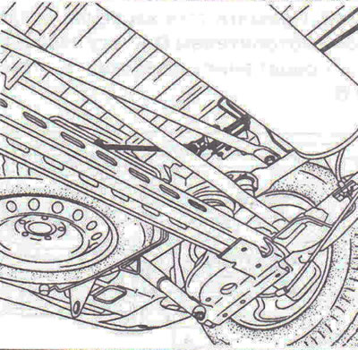
Figure 8.10. Unscrew the nut of the ball end of the brake force regulator rod.

Figure 8.10. Unscrew the nut of the ball end of the brake force regulator rod.


2. Disconnect the lines from the brake force regulator.

3. Unscrew the brake force regulator mounting bolts and remove it.

Installation


4. Installation is carried out in the reverse order of removal.

Adjustment


5. The method of adjusting the brake force regulators currently used in aftermarket service is quite simple and requires only two pressure gauges, which should be connected to the brake circuit of the left front and right rear wheels.

6. Checking and adjustment is performed on a loaded vehicle without load, with a full fuel tank and with the driver in the cabin.

7. After a certain pressure is created in the front brake wheel cylinder by pressing the brake pedal, immediately read the pressure readings in the rear brake wheel cylinder. Then move the regulator rod, having first loosened the tightening of the rod adjusting bolt.

8. This method is difficult to use when the vehicle is loaded, as is often the case with vans equipped with shelves filled with spare parts and tools. For vans, another adjustment method has been developed based on deflection calculations (deformation index) tires (this is an inexpensive but attention-grabbing method). The dependence of the pressure in the rear brake wheel cylinders on the load on the rear axle and the deformation of the tires must be taken into account.


Tightening torques


Brake line connection nuts - 14 Nm.

Brake force regulator mounting bolts - 18 Nm.

Tie rod adjustment bolt - 10 Nm.

Ball joint nut -10 Nm.

[Article posted on a web portal: OpelBook]


This article is available at russian, bulgarian, belarusian, ukrainian, serbian, croatian, romanian, polish, slovak, hungarian
Checking the article: Meshcheryakov Damir

Share information:

Previous articles
Opel Vivaro A: Brake system
Next articles

Removal and installation the parking brake system drive
Removal and installation the brake pedal
Removal and installation a vacuum pump
Removal and installation the brake booster
Removal and installation the master brake cylinder
Removal and installation rear brake pads


See similar ones from other Opel car manuals:
▶ Removal, installation and adjustment of the pressure… Opel Astra G (1998-2004)
▶ Pressure regulator valve in the hydraulic circuits of the… Opel Corsa B (1993-2000)
▶ Speedometer drive unit, band brake servo regulator,… Opel Kadett E (1984-1995)
▶ Brake force regulators Opel Vectra A (1988-1995)
▶ Brake and clutch fluids Opel Insignia A (2008-2017)
Link to this page in different formats

Visitor comments


No comments yet


How much will 48 + 38 =


Vivaro A (2001-2014) 
  • General information
  • User manual
  • Power unit
  • Petrol engine F4R
  • Diesel engine F9Q
  • Diesel engine G9U
  • Transmission
  • Clutch and drive shafts
  • Manual gearbox
  • Chassis
  • Front suspension
  • Rear suspension
  • Brake system
  • Body
  • Exterior
  • Interior
  • Electrical equipment
  • Heating and ventilation
  • Air conditioner
  • Equipment and devices
  • Electrical diagrams
Ascona C (1981-1988) 
  • General information
  • Maintenance
  • Power unit
  • Gasoline engines
  • Diesel engines
  • Cooling system
  • Fuel and exhaust system
  • Contact ignition system
  • Contactless ignition system
  • Transmission
  • Clutch
  • Mechanical gearbox
  • Automatic gearbox
  • Drive shafts
  • Chassis
  • Steering
  • Brake system
  • Car suspension
  • Body
  • Exterior
  • Interior
  • Doors and windows
  • Electrical equipment
  • Equipment and devices
  • Power devices
  • Electrical circuits
Frontera B (1998-2004) 
  • General information
  • User manual
  • Maintenance
  • Power unit
  • Petrol engines 2.2 l
  • Petrol engines 3.2 l
  • Diesel engines 2.2 l
  • Cooling system
  • Fuel system (petrol)
  • Fuel system (diesel)
  • Ignition system
  • Transmission
  • Clutch
  • Manual gearbox MUA5C
  • Automatic gearbox 4L30E
  • Chassis
  • Suspension and axles
  • Steering
  • Brake system
  • Body
  • Exterior
  • Interior
  • Doors, locks and windows
  • Heating and air conditioning
  • Electrical equipment
  • Power devices
  • Equipment and devices
  • Lighting and signaling
  • Electrical diagrams
Frontera A (1991-1998, petrol) 
  • General information
  • Introduction to guide
  • User manual
  • Maintenance
  • Power unit
  • Engine repair
  • Lubrication system
  • Cooling system
  • Power and exhaust system
  • Engine electrics
  • Transmission
  • Clutch
  • Mechanical gearbox
  • Cardan shafts
  • Chassis
  • Brake system
  • Front suspension
  • Rear suspension
  • Steering
  • Body
  • Repair and care
  • Electrical equipment
  • Equipment and devices
  • Electrical circuits
OpelBook.ru © 2017–2026 · Mobile version · · Sitemap: EN BG BY UA RS HR RO PL SK HU · Feedback · Site search
Astra F, petrol · Astra G, petrol · Astra G · Astra H · Astra J, petrol · Corsa B · Corsa C, petrol · Corsa C · Insignia A · Kadett D · Kadett E · Omega A · Omega B · Omega B2 · Vectra A, petrol · Vectra A · Vectra B, petrol · Vectra B · Vectra C · Zafira A, petrol · Frontera A, petrol · Frontera B · Ascona C · Vivaro A ·
We want your visit to be comfortable 🤝! We use cookies 🍪 to make that happen.