


The air supplied by the ventilation system to the vehicle interior can be heated or cooled depending on the comfort conditions selected by the driver and passengers. The heating and air conditioning systems are separate, but the units and components of these systems are located in one housing under the instrument panel.
The entire flow of air supplied to the cabin is directed for heating or cooling through the same casing.
The heat generated during engine operation is transferred by the coolant to the heater radiator located in the passenger compartment. The supplied air flow from the ventilation system passes through the radiator and is heated by the heat of the engine coolant flowing inside the radiator.
The air conditioning system removes excess heat and moisture from the interior according to basic physical principles. The refrigerant, circulating as a liquid in the high-pressure part of the system, evaporates and turns into a gas in the low-pressure section. When the gas expands, cooling occurs, accompanied by the removal of heat from the air supplied by the fan to the passenger compartment and a decrease in its temperature. Further, as it passes through the condenser, the refrigerant gives off the absorbed heat to the surrounding air. The heat extraction cycle continues indefinitely as the refrigerant circulates through the closed circuit. Moisture is removed from the air supplied to the passenger compartment due to condensation on the evaporator of the refrigeration chamber.
The compressor is driven by a belt from the crankshaft through a clutch pulley. The compressor pulley rotates continuously but does not drive the compressor shaft until the clutch electromagnetic winding is excited. To energize the clutch winding, voltage is applied and the clutch disc/hub assembly is moved back toward the pulley. The magnetic force locks the clutch disc and pulley into one unit, causing the compressor shaft to move. The rotation of the compressor shaft causes the low pressure refrigerant gas in the evaporator to be compressed and exit the compressor under high pressure. The refrigerant also releases oil, which is used to lubricate the compressor.
The air conditioning system is a potential hazard. When servicing it, certain rules must be followed. Most air conditioning system repair and maintenance operations require specialized equipment and certain skills.
The body ventilation is provided by forming a through air flow. Fresh air enters the vehicle through an air intake located in front of the windshield. The air flow is released to the outside through the exhaust ducts.
The amount of air flow is regulated by a fan.
To prevent fresh air from entering the car's interior, there is an air recirculation mode.
Security measures
Because R-134a refrigerant is a fluorinated hydrocarbon (HFC in which chlorine atoms are replaced by hydrogen atoms), then it does not have a harmful effect on the ozone layer of the atmosphere.
Refrigerant R-134a is a transparent, colorless substance in both liquid and gaseous phases. Since the boiling point of the refrigerant at atmospheric pressure is -29.8°C, under normal temperature and pressure conditions it is in a gaseous state.
This gas is heavier than air, it is non-flammable and non-explosive.
At normal temperature and atmospheric pressure, the evaporation rate of liquid refrigerant R-134a is so high that any object that comes into contact with it freezes. Therefore, special care must be taken when handling liquid refrigerant to prevent it from coming into contact with your skin and, especially, your eyes. Always wear safety glasses when servicing the air conditioning system. Also keep a bottle of pure, sterile mineral oil on hand. If liquid refrigerant gets into your eyes, rinse them immediately with a few drops of mineral oil. Oil quickly absorbs R-134a refrigerant. Then rinse eyes with plenty of cold water. Even if the irritation stops after these procedures, seek medical attention immediately.
Do not weld or hot-steam wash parts located in close proximity to air conditioning system components and hoses.
Warning! When filling the system, the R-134a refrigerant cylinder must be in a vertical position.
If the refrigerant cylinder is lying down or the valve is turned down, the refrigerant in the liquid phase will enter the air conditioning system and damage the compressor.
Warnings:
- To check for gas leaks in the air conditioning system, use an R-134a refrigerant leak detector.
- Avoid contact of liquid refrigerant with polished metal surfaces.
When liquid coolant gets on polished and chromed surfaces, they lose their shine and become dull, and when combined with moisture, they can lead to the appearance of corrosion spots on the entire surface of the metal.
Warning! Warnings specific to vehicles equipped with the Supplemental Restraint System (SRS).
- Improper maintenance or repair of any component of the SRS system(and also the SRS related component) may result in injury or death to service personnel (as a result of unauthorized deployment of the airbag), as well as the driver and front passenger (as a result of the SRS system not working properly after unqualified maintenance or repair).
- Maintenance or repair of any component of the SRS system (or a component associated with it) must only be performed by an authorized Opel dealer.
The SRS system consists of the following components: SRS control unit, air bag modules, coil wire and connecting wires.
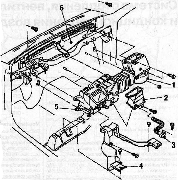
Location of heating and ventilation system elements in the car interior: 1 - Fan unit; 2 - air duct for supplying air to the lower part of the cabin; 3 - air duct for supplying air to the driver's knees; 4 - air duct for supplying air to the feet of rear passengers; 5 - heater unit; 6 - air duct for supplying air to the windshield.
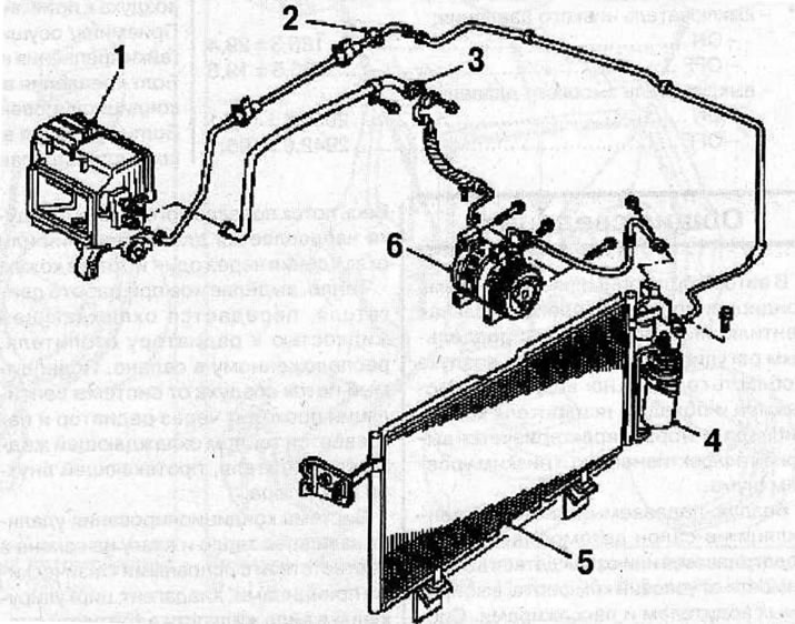
Location of heating, ventilation and air conditioning system components in the engine compartment: 1 - evaporator; 2 - high pressure service nipple; 3 - low pressure service nipple; 4 - receiver/dryer; 5 - condenser; 6 - compressor.
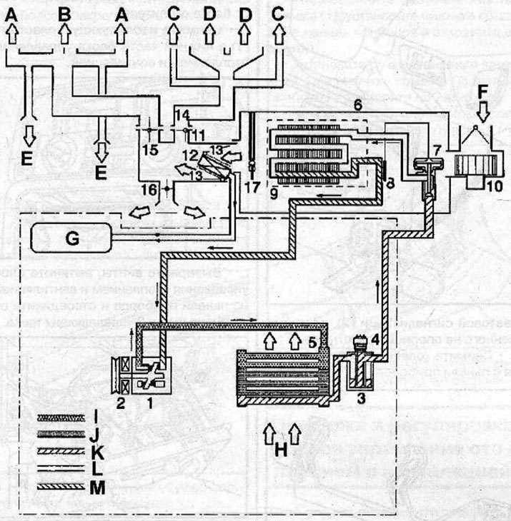
Schematic diagram of refrigerant circulation in the air conditioning system: 1 - compressor; 2 - electromagnetic clutch; 3 - battery; 4 - dual pressure sensor; 5 - condenser; 6 - evaporator block; 7 - expansion valve; 8 - temperature sensor; 9 - evaporator core; 10 - fan motor; 11 - heater unit; 12-heater core; 13 - temperature control flap; 14 - Defrost control valve (DEF); 15 - ventilation mode control flap (VENT); 16 - Heating mode control flap (HEAT); 17 - electronic thermostat; A - side ventilation grilles; B - central ventilation grilles; C - side defrosting grilles; D - defrosting grates; E - air supply grilles to the knee area; F - fresh air intake; G - fan motor; H - cooled air; I - gas under high pressure and high temperature; J - a mixture of gas and liquid under high pressure and high temperature; K - liquid under high pressure; L - a mixture of gas and liquid under low pressure and low temperature; M - gas under low pressure and low temperature
Visitor comments