
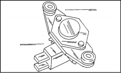
Bosch generator assembly diagram
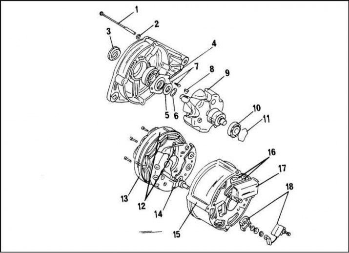
1 - Coupling bolt; 2 - washer; 3 - remote ring; 4 - bearing fastening bar; 5 - ring; 6 - distance ring; 7 - bolt and spring washer; 8 - key; 9 - rotor; 10 - bearing; 11 - washer; 12 - stator with rectifier diodes; 13 - stator; 14 - block of rectifiers; 15 - generator housing; 16 - brushes; 17 - voltage regulator; 18 - anti-interference capacitor
Disassembly
1. In accordance with illus. the following works are performed:
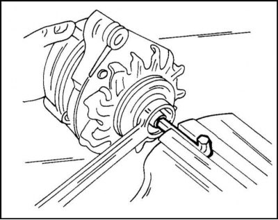
2. Unscrew the nut from the rotor shaft and remove the pulley and fan with a spacer from the shaft. You can keep the shaft from turning by throwing an old belt over the pulley and holding it in a vise. You can also insert a socket wrench into the shaft hole and unscrew the nut with a spanner wrench, as shown in illustration. To remove the pulley, a two- or three-jaw puller is used.
3. Remove the key from the shaft.
4. Disconnect the voltage regulator with brush holder. The brush holder is located on the reverse side and is fastened with two screws.
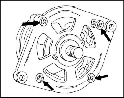
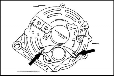
5. Mark the mutual position of the cover on the drive side and the generator housing and unscrew the coupling bolts from the housing (arrows in illustration.). Disconnect the rear bearing cover from the front cover. To do this, lightly tap the lid with a plastic mallet.
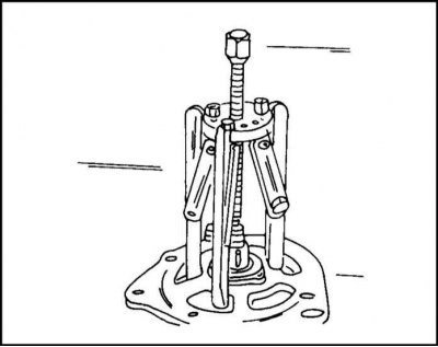
6. Place the drive side cover and rotor under the press and remove the rotor with a three-jaw puller as shown in illustration. When pressing out, the bolts of the outer washer of the bearing fastening break off. Care must be taken to ensure that the jaws of the puller are brought under the washer, and not just under the cover. If it is necessary to remove the bearing from the cover, unscrew the bolts from the inside and press the bearing out.
7. Remove the bearing from the opposite end of the rotor. If a puller is used for this, then bring its cams under the inner ring of the bearing.
8. Unsolder the rectifier block from the stator. To do this, clamp the wire between the stator and the soldering iron tip with heat sink tweezers. Diodes should not overheat.
The rectifier unit is removed only if you have the necessary experience and tools.
Repair of brushes and brush holders
1. Check the quality of contact between brushes and slip rings. Check the freedom of movement of the brushes in the guides of the brush holders. If necessary, clean with liquid "Tri".
If the protruding part of the brush is worn up to 5 mm (illustrations), it is necessary to replace the brush by unsoldering it.
Rotor check
1. If the slip rings are greasy, then it is necessary to clean them with a cloth soaked in liquid "Tri". If there are scratches, sand them with sandpaper.
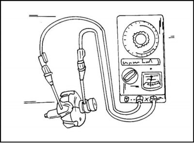
To check the insulation of the excitation winding of the rotor, attach one ohmmeter probe to the rotor core, and the other probe to the slip ring. The ohmmeter should show "infinity". Otherwise the rotor must be replaced (illustrations).
2. To check the excitation winding of the rotor for an open, attach both tips of an ohmmeter to the slip rings. The device should show 2.6 - 2.8 ohms. If the ohmmeter shows "infinity", then this indicates a break in the windings, if it shows "zero" for a short circuit (illustrations).
Stator check
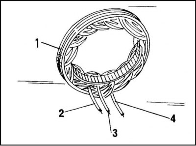
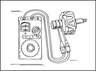
1. If there is a short circuit in the stator winding due to overheating, this can be established visually. This stator needs to be replaced. Attach one ohmmeter probe to the collector ring (1), the other in turn to each of the three stator terminals (2), (3), (4), (illustrations).
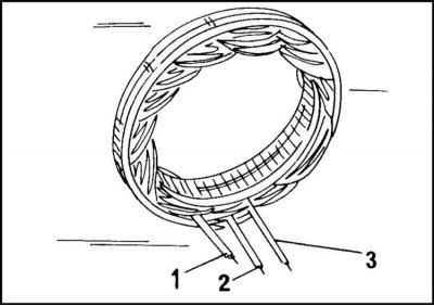
2. The instrument should show "infinity". To check the stator winding for an open circuit, alternately connect the stator leads to each other. If the device does not give readings, then this indicates the presence of a break (illustrations). Winding resistance should be 0.10 - 0.11 ohm.
Checking the rectifier unit
An accurate check of the value of the transmission voltage 45 and the value of the locking current of the diodes requires a special device and must be carried out in a car repair shop.
Assembly
1. The generator assembly diagram is shown in fig. "Bosch generator assembly diagram". Press the bearing onto the rotor shaft. The bearing in the cover on the drive side is secured with an outer washer. After installing the cover on the drive side, a spacer ring is pressed onto the end of the shaft (3). Before installing the generator on the car engine, it is necessary to check its operation on the stand.
Brush replacement
1a. As a result of long-term operation, the brushes wear out, reaching the minimum allowable size. Brushes can be replaced without alternator repair. However, it is not recommended to carry out this work on Delco-Remy generators, as this may cause certain difficulties. Here it is necessary to remove the generator and hand it over to a car repair shop.
On a Bosch generator, this work can be done after the generator has been removed. However, this requires soldering experience. Remove the two screws from the back of the alternator shown in fig. arrows
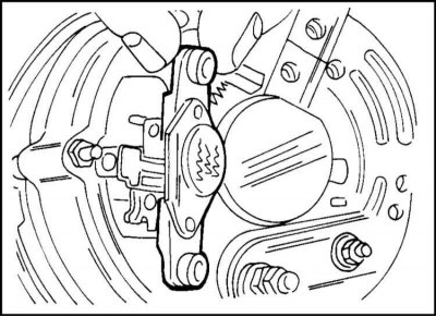
1b. Remove the assembly shown in fig. This is a brush holder and voltage regulator assembly.
2. Measure the length of the protruding part of the brushes. If the specified length is less than or close to 5 mm, the brushes must be replaced. If the length is sufficient, check the freedom of movement of the brushes in the brush holder guides. They must return back under the action of the tension of the springs. If this does not happen, the brushes are also replaced.
3. To replace the brush, it must be unsoldered. To do this, take a brush cable with tweezers (for heat sink) and solder it.
Insert new brushes with springs into the brush holder guides. Check that the brushes are not stuck. In the presence of jamming, clean the surfaces of the brush with fine sandpaper.
4. Solder the brush wire. Make sure that the solder does not leak along the cable, because. the cable will become too stiff.
Wipe the contact rings through the holes in the generator with a cloth soaked in gasoline and insert the brush holders into place. Make sure that the brushes are on the slip rings. Install the generator to the engine.
Note: Carefully check that the brushes are in place.
Visitor comments