
Engine 1.3
1. Remove the spark plugs.
2. Unscrew the screws securing the distributor cover and remove it.
3. Put the car in gear, turn off the handbrake and push the car forward until your finger is placed on the spark plug hole of cylinder No. 1 (cylinder closest to the crankshaft pulley), will not feel pressure. Continue to move the car forward until the mark on the crankshaft pulley aligns with the indicator (see photo). (On models with an automatic transmission, turn the engine using a wrench placed over the crankshaft pulley bolt). If you temporarily replace the distributor cap, the slider should be opposite the electrode corresponding to the ignition wire of spark plug No. 1.
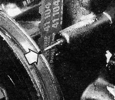
Photo 17.3. Notch on crankshaft pulley (shown by arrow) combined with the pointer.
4. Disconnect the distributor wiring at the ignition coil (see photo) and disconnect the vacuum tube of the vacuum regulator from the distributor.
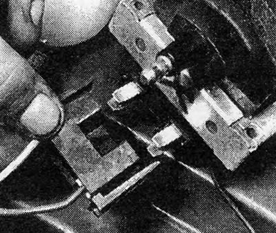
Photo 17.4. Disconnecting the distributor wiring from the ignition coil.
5. Unscrew the clamping nut (or bolt) distributor, remove the clamping plate and remove the distributor from the camshaft housing (see photo).
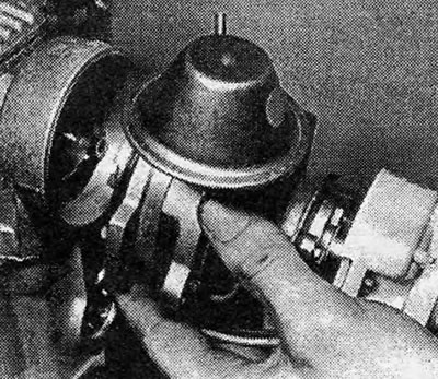
Photo 17.5. Removing the distributor from the camshaft housing.
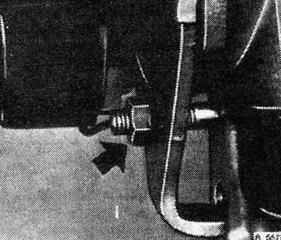
Pic. 4.5. Distributor clamping nut (shown by arrow) — engine 1.3
6. Before installing the distributor, check whether the engine remains in the same position, and if you accidentally moved it, return the engine to its original position (see paragraph 3).
7. Place the distributor so that the rotor contact is in line with the arrow or notch on the distributor body (see photo). In this case, the tongue on the distributor drive coupling will be in the desired position in order to fit into the corresponding slot on the camshaft (see photos).
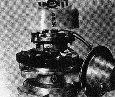
Photo 17.7A. Rotor contact and arrow on distributor body (circled) are on the same line...
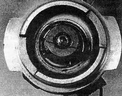
Photo 17.7B....due to which the protrusion on the distributor drive coupling takes the position...
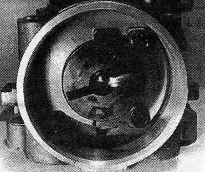
Photo 17.7C....allowing it to fit into the slot on the camshaft.
8. Check that the O-ring is in place on the distributor body and install the distributor in its place in the camshaft housing. Making sure that the rotor contact is still in line with the mark on the distributor body, install and secure the distributor clamping plate.
9. Reinstall the distributor cover, spark plugs and ignition wires, connect the distributor wiring and vacuum tube.
10. Adjust the ignition (see section 19).
Engines 1.6 and 1.8
11. The procedure is similar to that described above for the 1.3 engine, except for the following.
12. The distributor wiring must be disconnected from the distributor, and not from the ignition coil (see photo).
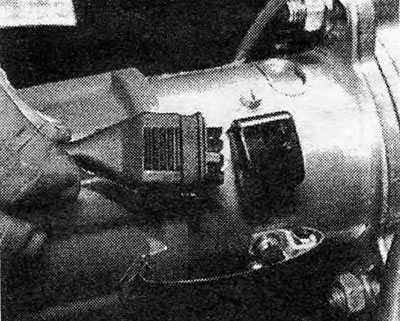
Photo 17.12. Disconnecting the low voltage plug (engines 1.6 and 1.8).
13. The distributor cover is secured not with screws, but with two spring clips (see photo).
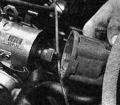
Photo 17.13. Removing the distributor cover (engines 1.6 and 1.8)
14. On the distributor body there is a mark for installing the rotor in the position corresponding to the flash in cylinder No. 1, however, in order for it to become visible, it is necessary to remove the rotor and the flash protection screen (see photo). Once the screen is removed, the rotor can be reinstalled to check its position.
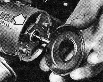
Photo 17.14. Removing the anti-flash shield to reveal the mark for cylinder #1 (shown by arrow) (engines 1.6 and 1.8).
15. The distributor is secured with two nuts, not a clamping plate (see photo).
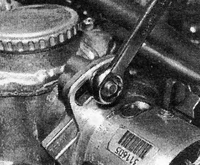
Photo 17.15. Removing the upper nut securing the distributor (engine 1.6/1.8).
16. The distributor is driven by a protrusion that fits into a slot on the camshaft, and not by a pawl (see photo).
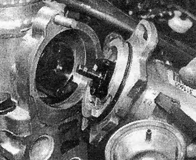
Photo 17.16. Removing the distributor - note the protrusion that fits into the slot in the camshaft (engine 1.6/1.8).
Visitor comments