
2. The main parts of the contactless ignition system are the control unit, the ignition coil and the distributor driven by the camshaft.
3. The system uses very high voltage and therefore, when working with it with the ignition on, appropriate precautions should be taken.
4. The Hall effect system consists of a permanent magnet, a detector/amplifier and a 4-blade impeller. When one of the vanes closes the detector/amplifier, no voltage is generated in the detector and the control unit passes current through the low voltage winding of the coil.
5. Due to the rotation of the impeller, the blade stops covering the detector and it falls into the magnetic field of a permanent magnet. Due to the Hall effect, a small voltage appears in the detector plate, which then increases and causes the control unit to interrupt the flow of current to the primary winding of the coil.
6. The control unit includes a circuit that turns off the low voltage circuit if the time interval between two consecutive signals exceeds 1.5 seconds. That. The coil and internal circuits are protected in case you inadvertently leave the ignition on.
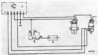
Pic. 4.6. Diagram of the Bosch electronic ignition system: 1. Control unit; 2. Ignition coil; 3. Distributor; 4. Battery; 5. Ignition switch.
7. We recommend limiting disassembly of this type of system distributor to those operations specified in the following sections.
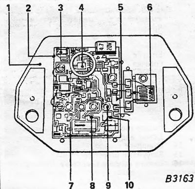
Pic. 4.7. Bosch electronic ignition control unit: 1. Metal backing; 2. Thick film board; 3. Capacitor chip; 4. Regulator for closed contact state; 5. Precision resistor (for current measurement); 6. Transistor output stage; 7. Conductors; 8. Diode chip; 9. Contacts for connecting wires; 10. Zener diode chip.
8. The ballast resistor is not used with contactless ignition systems, but sometimes it can be found on them as part of other wiring. When you locate a ballast resistor, keep in mind that it serves no function and can be ignored.
Visitor comments