
Engine 1.3
1. Remove the distributor from the engine (see previous section).
2. Unscrew the 2 mounting screws and remove the rotor.
3. Disconnect 2 electrical plugs from the ignition module (one on each side of the module).
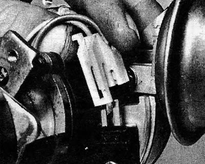
Photo 18.3. Disconnecting the electrical plug from the ignition module.
4. Remove 2 screws securing the module (see photo), and remove it from the distributor.
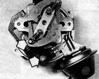
Photo 18.4. Screws securing the ignition module (shown by arrows).
5. Remove two screws securing the vacuum regulator (see photo), disconnect the rod and remove the regulator.
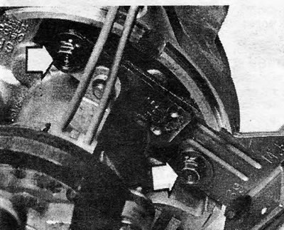
Photo 18.5. Screws securing the vacuum regulator (shown by arrows).
6. The design of the distributor in question does not allow further disassembly. You can replace the rotor, vacuum regulator, ignition module and distributor cap individually, but if inspection shows that any of the parts remaining on the distributor also need repair or replacement, you will have to replace the distributor assembly.
7. Inspect the distributor cover for corrosion of the electrodes and traces of tracking (thin black lines between electrodes). Check to make sure "ember" in the center of the lid could move freely and protruded from the holder. Replace the cover if necessary.
8. If the metal part of the rotor is severely burned or falls off, replace the rotor. A slightly burnt rotor can be cleaned with a fine file.
9. Suck the air out of the end of the vacuum tube and check that the rod is drawn inward. Stop sucking air and check that the rod returns to its original position. If the draft does not respond to vacuum, replace the vacuum regulator.

Pic. 4.9. AC Delco non-contact distributor mounted on a 1.3 engine: 1. Distributor cover; 2. Rotor; 3. Roller; 4. Pin; 5. Dog; 6. Spring; 7. Washer; 8. Spring; 9. O-ring; 10. Distributor body; 11. Seal; 12. Module (primary converter); 13. Induction sensor (magnetic resistance); 14. Retaining ring; 15. Vacuum regulator; 16. Plug to ignition coil.
10. Inspect the distributor body and shaft for excessive lateral play of the shaft in its bushings. Check that the weights of the centrifugal regulator can move freely and return to place under the influence of the springs. Check the fastening of all parts on the distributor shaft and inspect the protrusion on the drive coupling for wear.
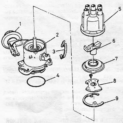
Pic. 4.10. The device of the Bosch contactless distributor installed on 1.6 l and 1.8 l engines: 1. Vacuum regulator; 2. Distributor body; 3. Distributor cover mounting clamp; 4. O-ring; 5. Distributor cover; 6. Rotor; 7. Anti-flash screen; 8. Upper support plate; 9. Support ring.
11. The distributor is assembled in the reverse order. Before installing the rotor, apply a few drops of engine oil to the centrifugal governor weight pins. If you are going to install a new ignition module, silicone lubricant should be included with it. This lubricant should be applied between the module and its housing to improve heat dissipation.
12. Install the assembled distributor into place (see section 17).
Models with 1.6 L and 1.8 L engines
13. Remove the distributor (see section 17).
14. Remove the slider and disconnect the flash protection screen.
15. Although the upper support plate can in principle be removed after its mounting screws have been removed, this operation is of purely academic interest, since There are no parts underneath that require adjustment, and there are no spare parts for these parts either.
16. If necessary, you can remove the vacuum regulator separately. Unscrew the 2 mounting screws and unhook the rod from the support plate (see photos). Please note that the screws are of different lengths - the longer screw also secures one of the distributor cap clamps.
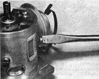
Photo 18.16A. Removing the Vacuum Regulator Mounting Screw (models with 1.6/1.8 l engines).
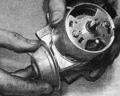
Photo 18.16B. Removing the Vacuum Regulator (models with 1.6/1.8 l engine).
17. Check the operation of the vacuum regulator (see paragraph 9).
18. Inspect the distributor cover and rotor (see paragraphs 7 and 8).
19. The distributor is assembled in the reverse order. Check that the vacuum regulator rod is correctly connected to the pin on the support plate (It is possible that connecting the rod will require several attempts).
20. Install the assembled distributor into place (see section 17).
Visitor comments