
Breakerless ignition system (1.8 and 2.0 l, since 1987) - general information
1. The types of ignition systems installed on large engine models from 1987 onwards are as follows:
- 1.8 l: EZ61 system (microprocessor timing system)
- 2.0 l: Motronic system
2. For each type of system, ignition timing is automatically adjusted and adjusted to existing conditions. This is achieved through a central computerized control system that collects information from various sensors and components and then adjusts the ignition timing as needed. Therefore, the ignition distributor simply acts as a high-voltage distributor.
3. When the Motronic system is installed, the control device also regulates the fuel requirements, which are described in Section 5.
Ignition system (1.8 and 2.0 liters, since 1987) - service
4. Maintenance requirements for the ignition system on models equipped with the EZ61 or Motronic system are minimal:
- (A) Periodically check high and normal voltage wires for cleanliness, continuity and tight connections
- (b) Check and replace spark plugs,
- (V) Clean and check the condition of the distributor cap and rotor arm at regular intervals.
Distributor (distributor) — (1.8 and 2.0 l, since 1987) - removal and installation
5. The ignition distributor on later models equipped with EZ61 or Motronic systems is different in that the vacuum and advance speed are controlled automatically by an electronic control device. Therefore, the ignition distributor on such models does not include any vacuum or centrifugal timing mechanisms. Its removal is carried out as follows.
6. Disconnect the high voltage wires from the spark plugs and the high voltage wire from the coil.
7. Unscrew the three screws securing the distributor cover and remove the cover (see photo 6.7).

Photo 6.7 Unscrew the fastening screws of the distributor cover
8. Remove the insulator. This is an intermediate mount in the casing, through an O-shaped spacer located in a groove along its periphery, so remove the insulator carefully so as not to damage the rotor (see photo 6.8).
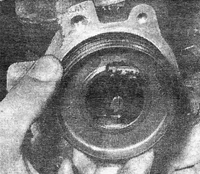
Photo 6.8 Pull out the insulator
9. Using a 3mm Allen wrench, remove the two screws and remove the rotor (see photo 6.9 A and B).
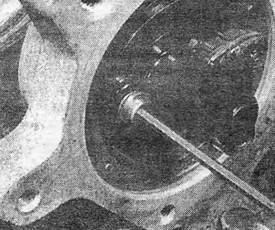
Photo 6.9 A Unscrew the two rotor screws...
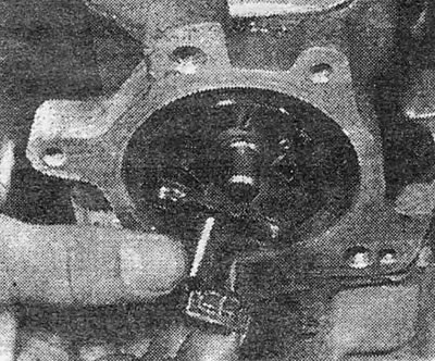
Photo 6.9 V... and remove the rotor
10. If the camshaft gasket needs to be replaced, remove the rotor lip by simply pulling it out, then carefully remove the oil gasket (see photo 6.10 A and B).
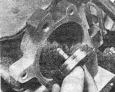
Photo 6.10 A Remove the rotor projection...
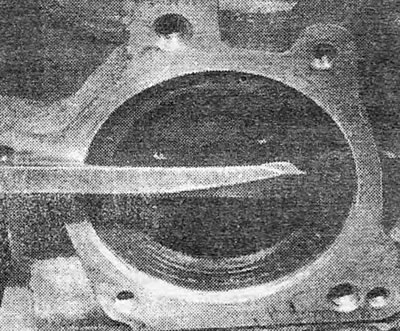
Photo 6.10 V... and remove the oil gasket
11. Clean the housing, then carefully insert the new gasket into place using a suitable tool. Be careful not to damage the casing.
12. Lubricate the oil gasket jaws, install the rotor lug, aligning the bolt holes in the rotor and lug with the bolt holes in the camshaft flange (see photo 6.12).
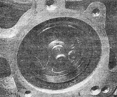
Photo 6.12 Align the bolt holes in the rotor boss and the camshaft flange
13. The remaining installation operations are carried out by performing the above steps in reverse order. Replace the spacer ring in the insulator groove if the old ring is damaged, then lightly lubricate it to make installation easier (see photo 6.13).
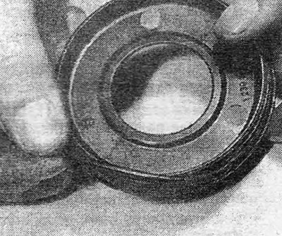
Photo 6.13 Replacing the insulator spacer ring
Ignition system monitoring device (1.8 l, 1987 release) - removal and installation
14. The ignition system control device on models with an engine capacity of 1.8 liters equipped with the EZ61 system is located on the right side of the engine compartment and is attached to the front suspension strut mount.
15. In order to remove the control device, release the clamp and disconnect the electrical wiring plug (see photo 6.15).

Photo 6.15 Disconnecting the electrical wiring plug of the control device
16. Unscrew the mounting screws and remove the device from its support bracket.
17. Reinstallation is carried out by performing the above steps in reverse order.
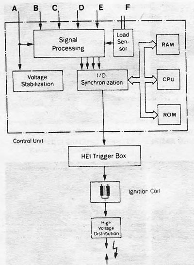
Figure 13.4. Diagram of the ignition timing control system with EZ61 microprocessor A. Battery voltage; B. Resistance (octane number); C. Coolant temperature; D. Engine speed; E. Throttle valve switch position; F. Vacuum inlet pipeline; CPU. Microprocessor; RAM. RAM; ROM. Permanent memory; I/O. Enter exit
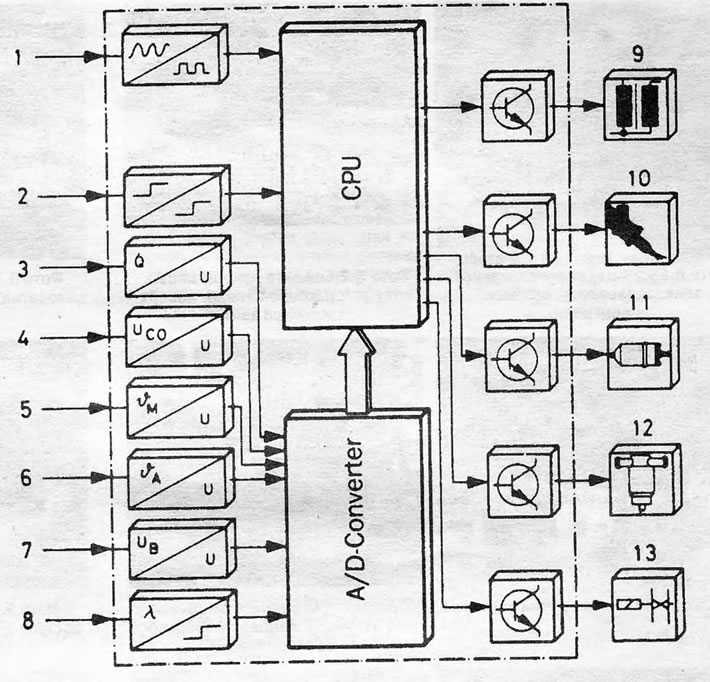
Figure 13.5. Design of the Motronic monitoring device Inputs: 1. Speed/ignition angle; 2. Transmission control; 3. Air flow; 4. Idle speed CO potentiometer; 5. Coolant temperature sensor; 6. Air inlet temperature; 7. Battery voltage; 8. Oxygen sensor (not for UK models). Outputs: 9. Ignition coil; 10. Fuel injector; 11. Fuel pump; 12. Idle speed regulator; 13. Fuel tank bleed valve (if installed)
Visitor comments