
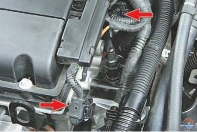
Engine crankshaft position sensor installed at the rear of the cylinder block inside the engine (against the rear of the crankshaft) on the rear crankshaft oil seal, which has a special design.
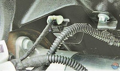
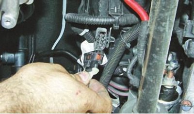
The sensor wiring harness block is located at the rear of the engine block (behind the starter).
If a malfunction occurs in the crankshaft position sensor circuit, the engine stops working, the ECU stores the fault code in memory and turns on the warning light in the instrument cluster.
You will need a hex wrench «for 4».
1. Disconnect the wire from the terminal «minus» battery.
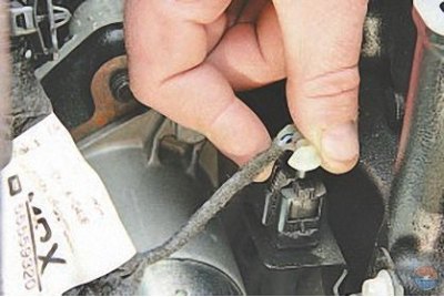
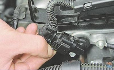
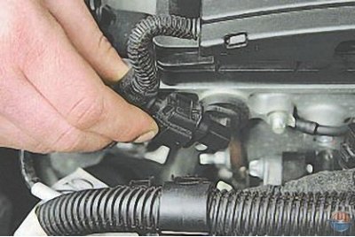
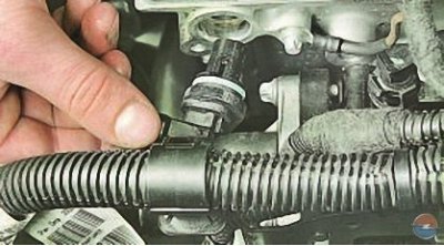
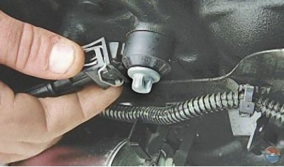
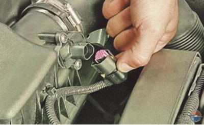
2. Squeeze the clamp of the sensor harness block..
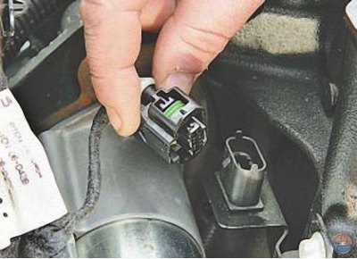
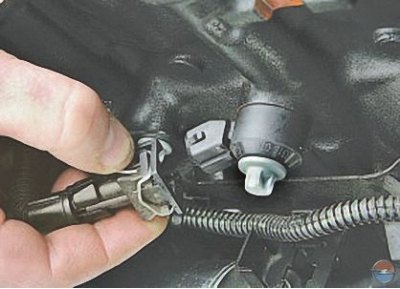
3.... and disconnect the harness from the sensor connector block.
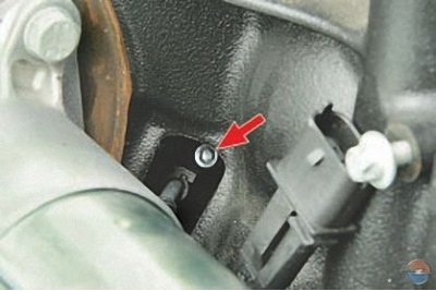
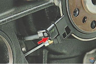
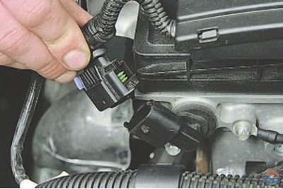
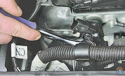
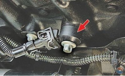
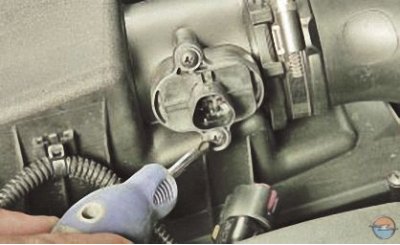
4. Remove the connecting block from the holder on the engine and unscrew the bolt securing the wiring harness seal to the cylinder block (shown by arrow).
5. Remove the gearbox (see Removal and installation of a transmission).
Note. In the process of removing the gearbox, the starter is removed.
6. On a car with a manual transmission, remove the clutch (see Removal and installation of clutch).
7. Remove the flywheel (see Removal, troubleshooting and installation of the flywheel).
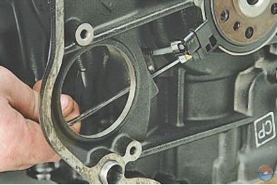
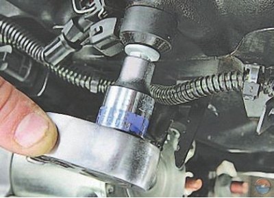
8. Turn out a bolt of fastening of the gauge to a back epiploon of a cranked shaft …
Note. For clarity, shown on the removed engine.
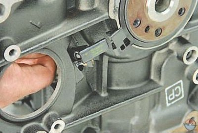
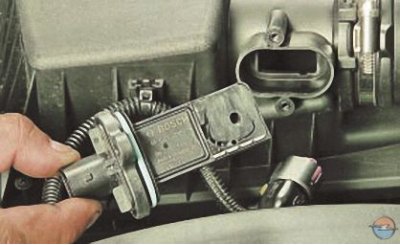
9.... and, having disconnected the sensor from the stuffing box, remove it by removing the seal of the sensor connecting block from the wall of the cylinder block.
10. Install the parts in the reverse order of removal.
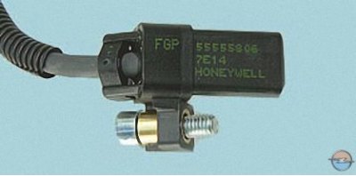
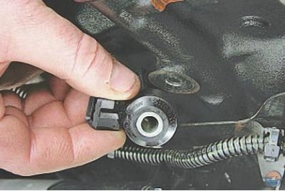
Note. Pay attention to the marking of the sensor. Get a new sensor with the same marking.
Camshaft Position Sensors (phase sensors) mounted on the rear end of the cylinder head. In the event of a malfunction in the circuit of one of the sensors, the ECU memorizes a fault code and uses a bypass engine management program (without changing the valve timing).
You will need: socket head TORX E10, screwdriver with a flat blade.
1. Disconnect the wire from the terminal «minus» battery.
2. Pull out the lock of the sensor harness block retainer..
3....squeeze the latch..
4.... and disconnect the block from the sensor.
5. Turn out a bolt of fastening of the gauge …
6.... and remove the sensor from the hole in the block head.
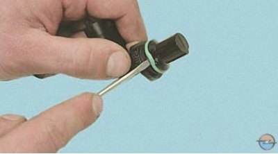
7. Prying with a screwdriver..
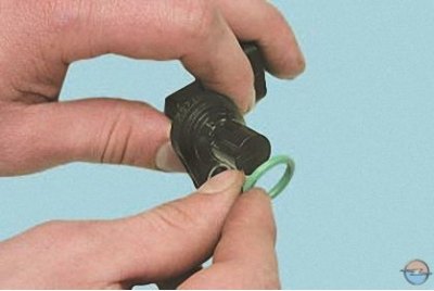
8.... remove the rubber sealing ring from the sensor.
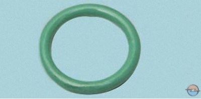
Note. Replace the sealing ring of the camshaft position sensor with a new one each time the connection is disassembled.
9. Install the parts in the reverse order of removal.
Knock sensor attached to the top of the cylinder block.
You will need a TORX E12 socket.
1. Disconnect the wire from the terminal «minus» battery.
2. Press the spring clip of the knock sensor wiring harness block..
3.... and disconnect the block from the sensor.
4. Loosen the bolt tightening the sensor to the engine block with the socket head..
5.... and, having unscrewed the bolt by hand, remove the knock sensor.
6. Install the knock sensor in reverse order. Tighten the sensor mounting bolt to 20 Nm.
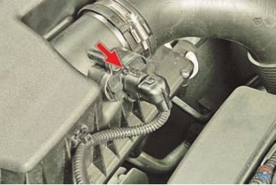
Temperature and mass air flow sensor installed in the air filter housing.
You will need a Phillips screwdriver.
1. Disconnect the wire from the terminal «minus» battery.
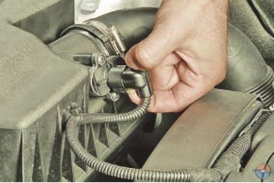
2. Squeeze the clamps of the sensor harness block..
3.... and disconnect the block from the sensor.
4. Turn out two screws of fastening of the gauge..
5.... and remove the sensor from the air filter housing.
6. Install the parts in the reverse order of removal.
Diagnostic oxygen sensor replaced in the following order.
You will need a key «at 22».
1. Disconnect the wire from the terminal «minus» battery.
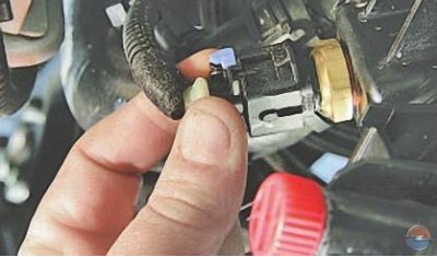
2. Squeeze the diagnostic oxygen sensor harness connector retainer and disconnect it from the engine harness connector.
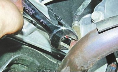
3. Loosen the sensor..
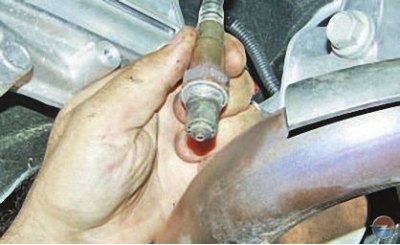
4.... and unscrew the sensor from the front pipe.
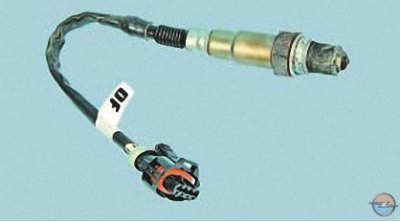
5. Install the diagnostic oxygen sensor in the reverse order of removal.
coolant temperature sensor, installed in the lower part of the right tank of the radiator of the cooling system, are replaced in the following order.
You will need a key «at 21».
1. Disconnect the wire from the terminal «minus» battery.
2. Drain the liquid from the engine cooling system (see Coolant replacement).
Note. When replacing the sensor, the coolant may not be drained: after removing the sensor, plug the hole with a finger or a plug - the loss of coolant will be minimal.
3. Press the retainer of the wiring harness block of the coolant temperature sensor..
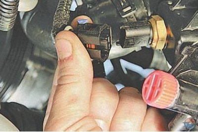
4.... and disconnect the block from the sensor.
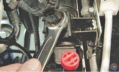
5. Loosen the sensor with a wrench..
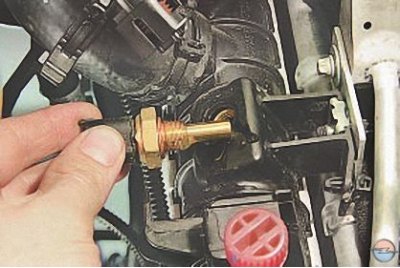
6.... and unscrew it from the opening of the radiator tank.
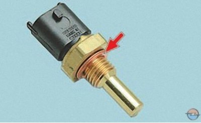
Note. Please note that the sensor is sealed with a figured copper ring. Replace the ring with a new one each time the sensor is removed.
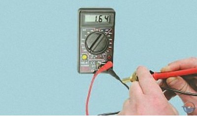
7. Cool the sensor down to ambient temperature. Connect the tester in ohmmeter mode to the sensor terminals and measure its resistance. Measure the current air temperature with a thermometer and compare the obtained values \u200b\u200bwith the data in Table. 1. If the resistance deviates from the norm, replace the sensor.
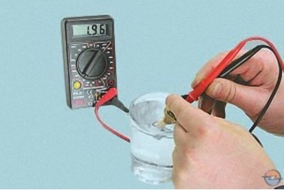
8. To measure the resistance at the sensor terminals under various temperature conditions, lower the sensor into hot water and check the change in its resistance as the water cools, controlling the water temperature with a thermometer. Nominal resistance values at various temperatures are shown in Table. 1.
Table 1. Data for checking the coolant temperature sensor
Air temperature,°С | Resistance, kOhm |
–20 | 13–17 |
0 | 5,3–6,7 |
20 | 2,3–3,0 |
40 | 1,0–1,5 |
60 | 0,56–0,76 |
80 | 0,3–0,42 |
9. If the resistance deviates from the norm, replace the sensor.
10. Screw in the coolant temperature sensor and tighten it to 12 Nm.
11. Connect the wiring harness block to the sensor.
12. Fill in coolant.
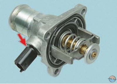
coolant temperature sensor, installed on the thermostat module, is a one-piece assembly with a thermostat cover. If the sensor fails, replace the cover or the thermostat assembly with the cover, depending on the design of the thermostat for a particular engine model (see Removal and installation of the thermostat).
Visitor comments