
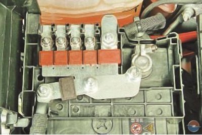
In addition, at the end of the wire «positive» the battery terminals are fitted with power circuit fusible links.
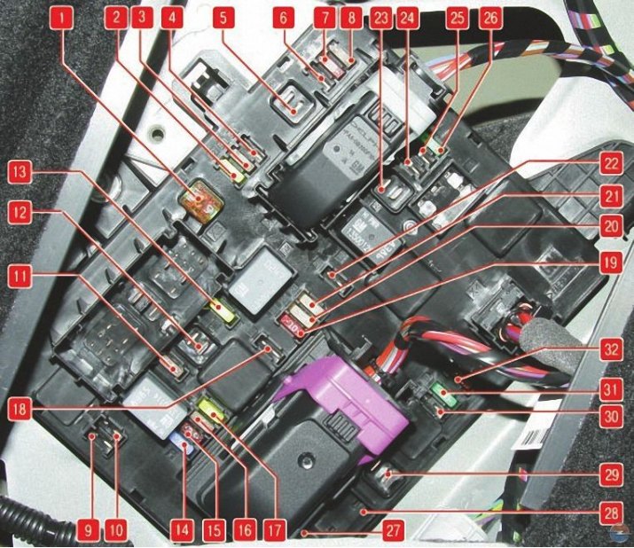
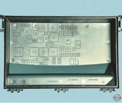
Pic. 1. Designations of fuses and fuses installed in the trunk mounting block
The designations of the fuses of the mounting block installed in the trunk under the lining of the left sidewall are shown in fig. 1.
Table 1. Purpose of fuses and fuses installed in the trunk mounting block
| № | Protected circuits |
| 1 | trailer module |
| 2 | trailer nest |
| 3 | Parking assistance |
| 4 | — |
| 5 | — |
| 6 | — |
| 7 | — |
| 8 | Anti-theft alarm |
| 9 | — |
| 10 | — |
| 11 | Trailer module, trailer socket |
| 12 | — |
| 13 | — |
| 14 | — |
| 15 | — |
| 16 | — |
| 17 | — |
| 18 | — |
| 19 | Steering wheel heater |
| 20 | roof hatch |
| 21 | Seat heating |
| 22 | — |
| 23 | — |
| 24 | — |
| 25 | — |
| 26 | — |
| 27 | — |
| 28 | — |
| 29 | — |
| 30 | — |
| 31 | Acoustic system |
| 32 | Active damping system, lane departure warning system |
In table. 1 shows the purpose of these fuses and fuse links, but on a specific car model, some of the circuits indicated in the table may not be available.
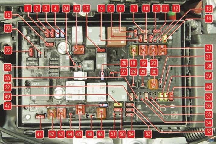
Pic. 2. Designations of fuses and fuse-links installed in the mounting block of the engine compartment
The designations of the fuses and fuses of the mounting block installed in the engine compartment are shown in fig. 2.
Table 2. Purpose of fuses and fuse-links installed in the mounting block of the engine compartment
| № | Protected circuits |
| 1 | The engine control unit |
| 2 | Oxygen concentration sensor |
| 3 | Fuel injection, ignition system |
| 4 | Fuel injection, ignition system |
| 5 | — |
| 6 | Heated mirrors |
| 7 | Fan controller |
| 8 | Oxygen concentration sensor |
| 9 | Rear window sensor |
| 10 | Battery sensor |
| 11 | Trunk release lever |
| 12 | Adaptive Front Lighting Module |
| 13 | — |
| 14 | Rear window cleaner |
| 15 | The engine control unit |
| 16 | Starter |
| 17 | transmission control unit |
| 18 | Rear window heating |
| 19 | Front power windows |
| 20 | Rear power windows |
| 21 | ABS |
| 22 | Left headlight (high beam) |
| 23 | headlight washer |
| 24 | Right headlight (dipped beam, xenon) |
| 25 | Left headlight (dipped beam, xenon) |
| 26 | Fog lights |
| 27 | Heating of diesel fuel |
| 28 | — |
| 29 | Electric parking brake |
| 30 | ABS |
| 31 | — |
| 32 | Airbag |
| 33 | Adaptive headlight system |
| 34 | — |
| 35 | Electric windows |
| 36 | — |
| 37 | Canister purge solenoid valve |
| 38 | Vacuum pump |
| 39 | Fuel system control unit |
| 40 | Windshield washer, rear window washer |
| 41 | Right headlight (high beam) |
| 42 | Engine cooling radiator fan |
| 43 | windshield wiper |
| 44 | — |
| 45 | Engine cooling fan |
| 46 | — |
| 47 | Sound signal |
| 48 | Engine cooling radiator fan |
| 49 | Fuel pump |
| 50 | Headlight corrector |
| 51 | Throttle assembly |
| 52 | Heating of crankcase gases |
| 53 | Transmission Control Module, Engine Control Module |
| 54 | Wiring control |
In table. 2 shows the purpose of these fuses and fuses, but on a particular car model, some of the circuits indicated in the table may not be available.
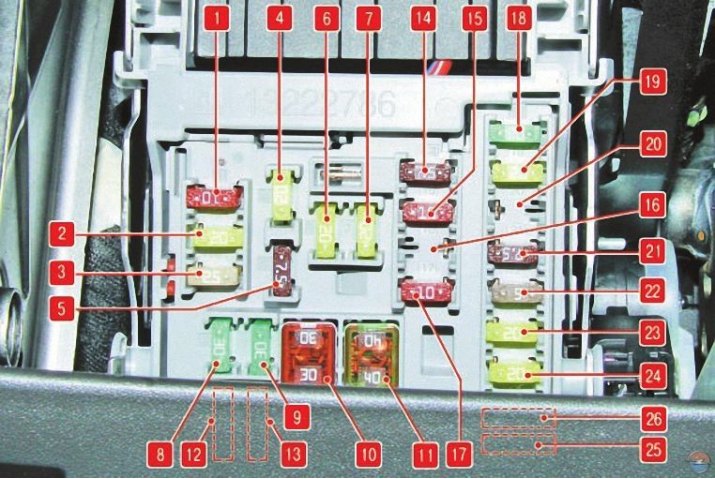
Pic. 3. Designations of fuses and fuse-links installed in the instrument panel mounting block
The designations of the fuses and fuse links of the mounting block installed in the instrument panel are given in fig. 3.
Table 3. Purpose of fuses and fuse-links installed in the instrument panel mounting block
| № | Protected circuits |
| 1 | Display |
| 2 | Outdoor Lighting |
| 3 | Same |
| 4 | Audio system |
| 5 | Information and measuring system |
| 6 | Power socket front |
| 7 | Rear power socket |
| 8 | Left headlight (dipped beam, halogen) |
| 9 | Right headlight (dipped beam, halogen) |
| 10 | Door locks |
| 11 | Heating systems (ventilation) and conditioning |
| 12 | — |
| 13 | — |
| 14 | Diagnostic connector |
| 15 | Airbag |
| 16 | — |
| 17 | Air conditioner |
| 18 | — |
| 19 | Brake lights, reversing lights, interior lights |
| 20 | — |
| 21 | Devices |
| 22 | ignition switch |
| 23 | Body electrical control unit |
| 24 | Same |
| 25 | — |
| 26 | — |
In table. 3 shows the purpose of these fuses and fuses, but on a particular car model, some of the circuits indicated in the table may not be available.
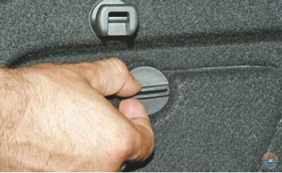
1. To gain access to the mounting block located in the trunk, turn 90°the lock of the sunroof cover in the upholstery of the left side panel..
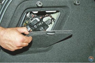
2.... and flip down the cover.
3. To gain access to the mounting block located in the engine compartment, press the two latches with a screwdriver..
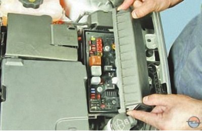
4.... and remove its cover.
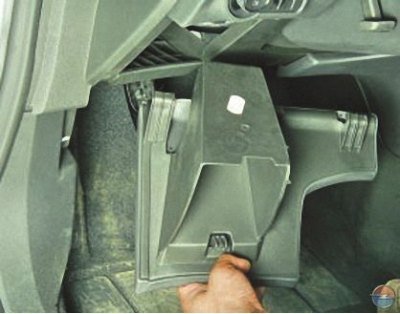
5. To gain access to the mounting block located in the instrument panel, remove the left glove box (see Removal and installation of glove boxes).
On the inside of the cover of the mounting block located in the engine compartment, there is a diagram of the location of fuses and fuses.
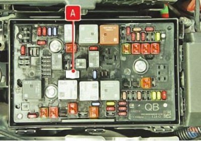
Tweezers are fixed in a special nest in the body of this mounting block A to remove fuses.
6. Before replacing a blown fuse or fuse, find out the cause of the blown and fix it. When looking for a malfunction, look at the ones listed in Table. 1-3 circuits that this fuse or fuse protects.
Attention! Do not replace fuses with fuses of a different amperage or homemade jumpers, as this may damage electrical appliances and even cause a fire.
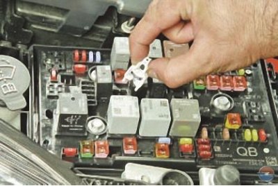
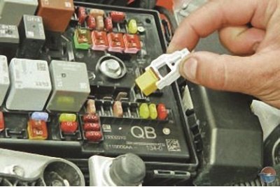
7. Remove the tweezers from the base of the mounting block located in the engine compartment.
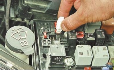
8. Grab the fuse with tweezers..
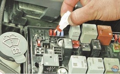
9.... and remove it from the connector.
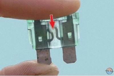
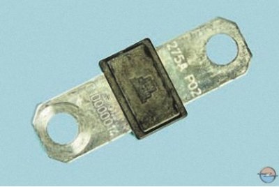
This is what a blown fuse looks like (the jumper shown by the arrow inside the holder has burned out and opened).
To replace a fuse, use a spare fuse of the same rating (and colors).
10. Install a fuse of the same rating as the removed one into the connector.
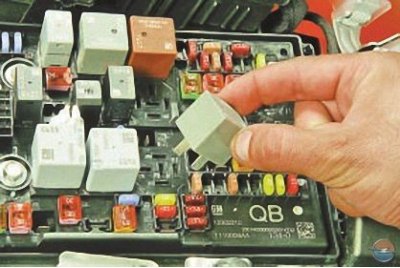
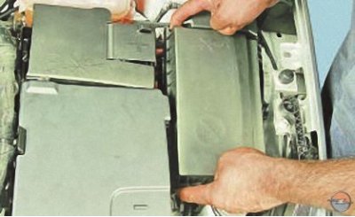
11. If replacement is necessary, remove the relay from the mounting block by rocking it from side to side..
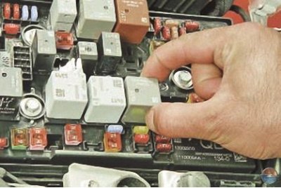
12.... and install a new relay.
13. Fusible inserts replace similarly replacement of the relay.
For replacement power fuse do the following.
You will need a socket «at 13».
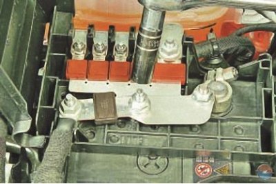
1. Loosen the two nuts securing the fuse..
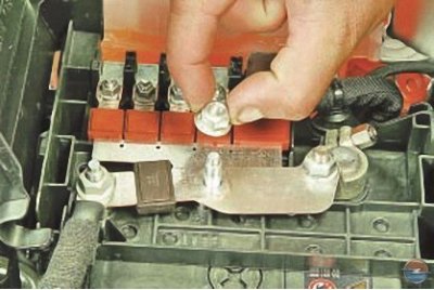
2.... unscrew both nuts..
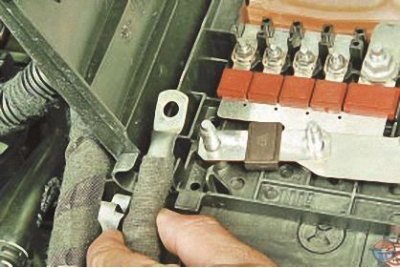
3.... disconnect the lug of the power wire..
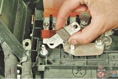
4.... and remove the power fuse.
5. Install a new power fuse in the reverse order of removal.
Visitor comments