


The control device in the system is the electronic control unit (ECU). The amount of fuel supplied by the injectors is regulated by an electric pulse signal from the ECU. The electronic unit monitors data on the engine condition, calculates the fuel requirement and determines the required duration of fuel supply by the injectors (pulse duration - duty cycle). To increase the amount of fuel supplied, the ECU increases the pulse duration, and to reduce the fuel supply, it shortens it. In addition, in accordance with the embedded algorithm, the ECU controls the operation of the electric motor of the engine cooling system fan and the electromagnetic clutch of the air conditioner compressor, performs the self-diagnosis function of the system elements and notifies the driver of any malfunctions.
If individual sensors and actuators fail, the ECU switches on emergency modes to ensure engine operability.
The ECU has the ability to evaluate the results of its calculations and commands, remember the modes of recent operation and act in accordance with them. "Self-learning" or adaptation of the ECU is a continuous process, but the corresponding settings are stored in the RAM of the electronic unit until the first power outage of the ECU.
The engine management system, along with the electronic control unit, includes sensors, actuators, connectors and fuses.
Fuel is supplied using one of two methods: synchronous, i.e. at a certain position of the crankshaft, or asynchronous, i.e. independently or without synchronization with the rotation of the crankshaft. Synchronous fuel injection is the most commonly used method. Asynchronous fuel injection is used mainly in the engine start mode. The ECU switches on the injectors sequentially. Each of the injectors is switched on every 720° of crankshaft rotation. This method allows for more accurate dosing of fuel to the cylinders and reduces the level of toxicity of exhaust gases.
The amount of fuel supplied is determined by the engine condition, i.e. its operating mode. These modes are provided by the ECU and are described below.
When the engine crankshaft begins to rotate with the starter, the first pulse from the crankshaft position sensor causes a pulse from the ECU to turn on all injectors at once, which allows the engine to start faster.
The initial fuel injection occurs each time the engine is started. The duration of the injection pulse depends on the temperature. On a cold engine, the injection pulse increases to increase the amount of fuel, on a warm engine, the pulse duration decreases. After the initial injection, the ECU switches to the appropriate injector control mode.
Start mode. When the ignition is turned on, the ECU turns on the electric fuel pump relay, which creates pressure in the fuel supply line to the fuel rail.
The ECU checks the signal from the coolant temperature sensor and determines the amount of fuel and air required for starting.
When the engine crankshaft starts to turn, the ECU generates a phased pulse to turn on the injectors, the duration of which depends on the signals from the coolant temperature sensor. On a cold engine, the pulse duration is longer (to increase the amount of fuel supplied), and less when warmed up.
Enrichment mode during acceleration. The ECU monitors sudden changes in the position of the throttle pedal (by signal from the throttle pedal position sensor), as well as the signal from the mass air flow sensor and provides additional fuel supply by increasing the injection pulse duration. The enrichment mode during acceleration is used only to control fuel supply in transient conditions (when moving the throttle pedal).
Fuel supply shutdown mode during engine braking. When braking with the engine with the gear and clutch engaged, the ECU can completely disable the fuel injection pulses for short periods of time. The fuel supply is switched off and on in this mode when certain conditions are created for the coolant temperature, crankshaft speed, vehicle speed, and throttle opening angle.
Supply voltage compensation. When the supply voltage drops, the ignition system may produce a weak spark and the mechanical movement of the injector opening may take longer. The ECU compensates for this by increasing the energy accumulation time in the ignition module and the injection pulse duration.
Accordingly, when the battery voltage increases (or voltage in the vehicle's on-board network) The ECU reduces the energy accumulation time in the ignition module and the injection duration.
Fuel shut-off mode. When the engine stops (ignition off) the fuel is not supplied by the injector, thus eliminating spontaneous ignition of the mixture in an overheated engine. In addition, pulses to open the injectors are not supplied if the ECU does not receive "reference" pulses from the crankshaft position sensor, i.e. this means that the engine is not running.
The fuel supply is also cut off when the maximum permissible engine crankshaft speed is exceeded to protect the engine from running at unacceptably high speeds.
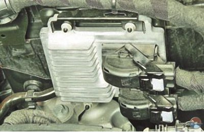
The electronic control unit (ECU) is located in the left part of the engine compartment on a bracket installed on the battery mounting shelf and is the control center of the electronic engine management system. The ECU is connected by electric wires to all the system sensors. Receiving information from them, the unit performs calculations in accordance with the parameters and control algorithm stored in the memory of the programmable read-only memory (EPROM) and controls the actuators of the system. The program version recorded in the EPROM memory is designated by the number assigned to this modification of the ECU.
The control unit detects the fault, identifies and stores its code, even if the failure is unstable and disappears (for example, due to poor contact). The engine management system malfunction indicator lamp in the instrument cluster goes out 10 seconds after the failed component has been restored to working order.
After repair, the fault code stored in the control unit memory must be erased. To do this, disconnect the power supply to the unit for 10 seconds (remove the fuse of the power supply circuit of the electronic control unit or disconnect the wire from the negative terminal of the battery).
The unit supplies various sensors and switches of the control system with direct current of 5 and 12 V. Since the electrical resistance of the supply circuits is high, the control lamp connected to the system terminals does not light. To determine the supply voltage at the ECU terminals, use a voltmeter with an internal resistance of at least 10 MOhm.
The ECU has the following types of memory:
- programmable read-only memory (EPROM);
- random access memory (RAM);
- electrically reprogrammable memory (ERPROM).
Programmable read-only memory (PROM). It contains a general program that contains a sequence of working commands (control algorithms) and various calibration information. This information is the data for controlling injection, ignition, idle speed and other parameters that depend on the weight of the car, the type and power of the engine, the gear ratios of the transmission and other factors. The EPROM is also called a calibration memory device. The contents of the EPROM cannot be changed after programming. This memory does not require power to save the information recorded in it, which is not erased when the power is turned off, i.e. this memory is non-volatile.
Random access memory (RAM). This is the ECU "notebook". The ECU microprocessor uses it to temporarily store measured parameters for calculations and intermediate information. The microprocessor can enter data into it or read it as needed.
The RAM chip is mounted on the ECU printed circuit board. This memory is volatile and requires uninterruptible power supply to be saved. When the power supply is interrupted, the diagnostic trouble codes and calculated data contained in the RAM are erased.
Electrically reprogrammable memory (ERPROM). Used for temporary storage of codes and passwords for the vehicle's anti-theft system (immobilizer). The password codes received by the ECU from the immobilizer control unit are compared with the codes stored in the EEPROM, as a result of which the engine starting is permitted or prohibited.
The EEPROM records such vehicle operating parameters as the vehicle's total mileage, total fuel consumption, and engine operating time.
The ERPZU also registers some malfunctions of the engine and the vehicle:
- engine overheating time;
- engine operating time on low octane fuel;
- engine operating time above maximum permissible speed;
- the time the engine is running with misfires of the fuel-air mixture, the presence of which is indicated by the exhaust gas toxicity excess warning lamp;
- engine operating time with a faulty knock sensor;
- engine operating time with a faulty oxygen concentration sensor;
- time of driving the vehicle at a speed exceeding the maximum permitted speed during the running-in period;
- the time the vehicle is moving with a faulty speed sensor;
- number of times the battery is disconnected with the ignition switch on.
EEPROM is a non-volatile memory, it can store information without power supply to the ECU.
The ECU is not suitable for repair; in case of failure it must be replaced.
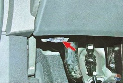
Diagnostic connector, located on the left under the instrument panel, is used to exchange data with the ECU. A scanning device is connected to the diagnostic connector to read information about errors stored in the ECU memory, to check sensors and actuators in real time, to control actuators and reprogram the ECU.
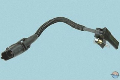
Crankshaft position sensor inductive type is designed to synchronize the operation of the electronic control unit with the TDC of the pistons of the 1st and 4th cylinders and the angular position of the crankshaft.
The sensor is installed at the rear of the engine, inside it, opposite the timing teeth on the crankshaft journal.
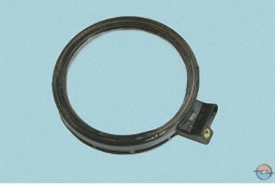
The sensor holder is a special rear crankshaft oil seal.
The master teeth are made on the surface of the neck at equal intervals. One tooth is missing to create a synchronization pulse (the "reference" pulse), which is necessary to coordinate the operation of the control unit with the TDC of the pistons in the 1st and 4th cylinders.
When the crankshaft rotates, the teeth change the magnetic field of the sensor, inducing AC voltage pulses. The control unit determines the crankshaft rotation frequency based on the sensor signals and sends pulses to the injectors.
If the sensor fails, the engine cannot be started.
Text copied from an internet website: www.opelbook.ru
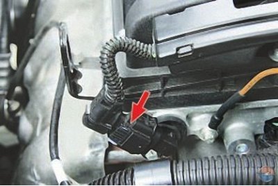
Camshaft position sensors (phase sensors) inductive type are used to organize phased fuel injection in accordance with the order of cylinder operation. The signals from the intake and exhaust camshaft sensors are also used by the controller to control the change in valve timing depending on the engine operating mode. If a malfunction occurs in the circuit of any of the sensors, the controller stores its code in its memory and turns on the signal lamp.
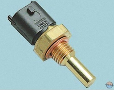
Coolant temperature sensor is a thermistor (a resistor whose resistance varies inversely with temperature). At low coolant temperatures (–40°C), the thermistor resistance is about 100 kOhm; when the temperature rises to +130°C, it decreases to 70 Ohm).
A special feature of Opel Astra engines is the installation of two coolant temperature sensors. The sensor shown in the photo is installed in the right tank of the engine cooling system radiator.
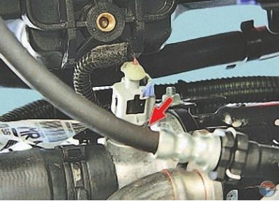
The second sensor is installed in the thermostat cover. At low temperatures, the resistance of the sensors is high, and at high temperatures, it is low.
The electronic unit supplies the temperature sensor circuit with a constant "reference" voltage. The sensor signal voltage is maximum on a cold engine and decreases as it warms up. Based on the voltage value, the electronic unit determines the engine temperature and takes it into account when calculating the injection and ignition adjustment parameters. If the sensor fails or there are problems in its connection circuit, the ECU sets a fault code and stores it.
In addition to the above, the sensor also indirectly serves as a coolant temperature gauge sensor in the instrument cluster. Based on the information from this sensor, the electronic engine control unit changes the position of the gauge needle.
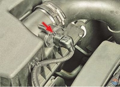
Combined mass air flow and intake air temperature sensor installed in the air hose between the air filter and the throttle assembly. The operating principle of the mass air flow sensor is based on maintaining a constant temperature of the resistors (the higher the air flow rate, the more current is required to maintain the resistor temperature). The operating principle of the incoming air temperature sensor is similar to the operating principle of the coolant temperature sensor. Depending on the readings of these sensors, the ECU adjusts the amount of fuel injected into the cylinder to obtain the optimal working mixture.
Manifold Absolute Pressure Sensor converts the vacuum in this pipe into electrical voltage, the value of which the ECU uses to determine the engine load. The sensor is mounted on the intake pipe. The output voltage of the sensor changes in accordance with the pressure in the intake pipe: from maximum (with the throttle fully open) to the minimum (with the damper closed). When the engine is not running, the control unit determines the atmospheric pressure from the sensor voltage and adapts the injection control parameters to the specific altitude above sea level. The atmospheric pressure values stored in the memory are periodically updated during uniform vehicle movement and during full throttle opening.
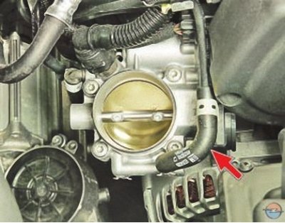
Throttle position sensor (for clarity, the air filter has been removed) is installed in the electric drive housing on the throttle assembly. The operating principle of the sensor is based on the Hall effect.
When the throttle valve is turned (from the impact on the control pedal), the voltage at the sensor output changes. When the throttle valve is closed, it is below 2.5 V. When the valve opens, the voltage at the sensor output increases; when the valve is fully open, it should be more than 4 V.
By monitoring the sensor output voltage, the controller adjusts the fuel supply depending on the throttle valve opening angle (i.e. at the driver's discretion).
The throttle position sensor does not require adjustment, since the control unit senses idle speed (i.e. complete closing of the throttle valve) as a zero mark.
Vehicle speed sensor is not available on Opel Astra J vehicles. The electronic control unit receives information about the vehicle's speed from the left front wheel speed sensor of the anti-lock braking system (ABS).
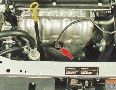
Oxygen concentration control sensor is used in the feedback injection system and is installed in the exhaust manifold. Information about the presence of oxygen in the exhaust gases is used to adjust the calculations of the injection pulse duration; this information is provided by the control oxygen concentration sensor. The oxygen contained in the exhaust gases reacts with the sensor, creating a potential difference at the sensor output. It changes from approximately 0.1 V (high oxygen content - lean mixture) to 1 V (low oxygen content - rich mixture).
Information from the sensor is sent to the control unit in the form of low and high level signals. When the signal is high level, (about 4.2 V) sensor at the inlet to the cat collector, the control unit receives information about the high oxygen content. Low level signal (about 2.2 V) this sensor indicates low oxygen content in the exhaust gases.
By constantly monitoring the voltage of the sensor signals, the control unit adjusts the amount of fuel injected by the injectors. When the sensor signal at the inlet to the catalytic collector is high, (lean air-fuel mixture) the amount of fuel supplied increases when the signal level is low (rich mixture) – decreases. If the sensor signal level at the neutralizer output does not correspond to the values allowed for the given operating mode, the control unit identifies a malfunction of the catalytic converter.
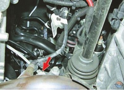
Oxygen Concentration Diagnostic Sensor installed in the intake pipe behind the neutralizer, operates on the same principle as the control sensor. The output characteristics of the sensor at the outlet of the catalytic collector are different: a high oxygen content corresponds to a low-level signal (about 0.1 V), and low oxygen content - a high level signal (about 0.9 V). The signal generated by the diagnostic oxygen sensor indicates the presence of oxygen in the exhaust gases after the catalytic converter. If the catalytic converter is working properly, the readings from the diagnostic sensor will differ significantly from the readings from the control sensor.

Knock sensor attached to the top of the cylinder block in the areas between the 2nd and 3rd cylinders and captures abnormal vibrations (detonation strikes) in the engine.
The sensitive element of the knock sensor is a piezoelectric crystal plate. During detonation, voltage pulses are generated at the sensor output, which increase with the increase in the intensity of detonation shocks. The controller, based on the sensor signal, regulates the ignition advance to eliminate detonation flashes of fuel.
Warnings
Before removing any fuel injection control system components, disconnect the negative battery cable.
Do not start the engine if the battery cable terminals are not tightly tightened.
Never disconnect the battery from the vehicle's electrical system while the engine is running.
When charging the battery, disconnect it from the vehicle's electrical system.
Do not expose the ECU to temperatures above 65°C when operating and above 80°C when not operating (for example, in a drying chamber). It is necessary to remove the ECU from the car if this temperature is exceeded.
Do not disconnect or connect wires to the ECU when the ignition is on.
Before performing electric welding work on the vehicle, disconnect the wires from the battery and the wiring harness connectors from the ECU.
All voltage measurements should be performed using a digital voltmeter with an internal resistance of at least 10 MOhm.
The electronic components used in the fuel injection system are designed for very low voltage and can therefore be easily damaged by electrostatic discharge. To prevent damage to the ECU, do not touch its terminals with your hands.
In all cases, a special scanner is required to diagnose the engine management system, so if any system malfunctions occur, contact a specialized service center.
Visitor comments