


Contents: Disassembly ⬇ Assembly ⬇
The shafts of the RK5 manual transmission are shown in the figure 5.34, shafts of the RK6 manual transmission - in Figure 5.35.
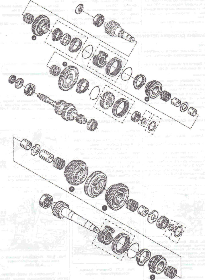
Figure 5.34. Shafts of the RK5 manual transmission.
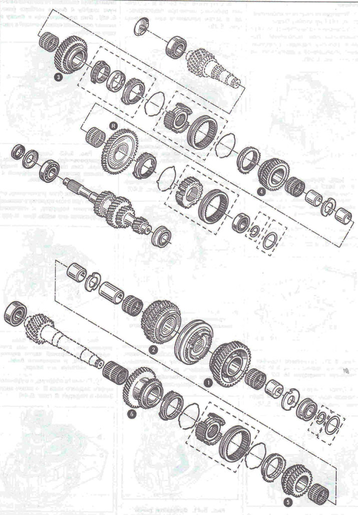
Figure 5.35. Shafts of the RK6 manual transmission.
Disassembly
1. Install the bracket plate B. Vi. 1417 on the Desvil rack.
2. With the B. Vi 1417 bracket in a horizontal position, place the gearbox with the side normally facing the engine on the plate (figure 5.36).
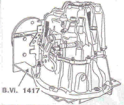
Figure 5.33. With the B. Vi 1417 bracket in a horizontal position, place the gearbox with the side normally facing the engine on the plate.
3. Fasten the gearbox to the bracket B.Vi.1417 using holes No. G2 and Z2 (figure 5.37).
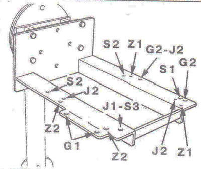
Figure 5.37. Fasten the gearbox to the B.Vi.1417 bracket using holes No. G2 and Z2.
4. Disconnect the nipple C of the clutch release drive slave cylinder by removing the retainer 3 (figure 5.38).
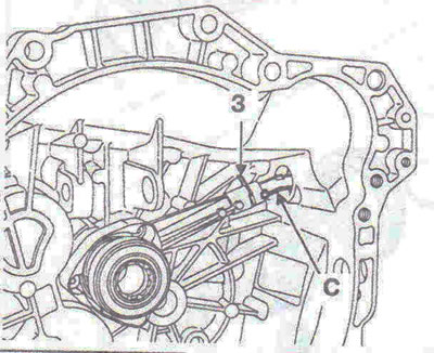
Figure 5.38. Disconnect the nipple C of the clutch release drive slave cylinder by removing the retainer 3.
5. Unscrew the three bolts B securing the hydraulic drive slave cylinder, and then remove the cylinder itself (figure 5.39).
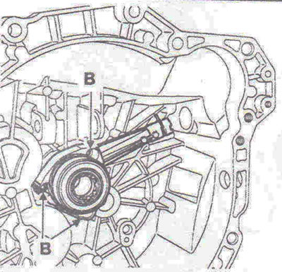
Figure 5.39. Unscrew the three bolts B securing the hydraulic drive working cylinder, and then remove the cylinder itself.
6. Remove the selector lever 1, the drive cable bracket 2 and the reversing light switch 4 (figure 5.40).
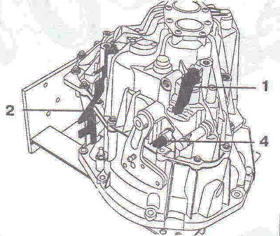
Figure 5.40. Remove the selection lever 1, the drive cable bracket 2 and the reversing light switch 4.
7. Unscrew the bolts securing the gearbox wiring connector.
8. Rotate the shift lever to release the control lever, while lifting the crankcase up, and then remove the crankcase completely (figure 5.41).
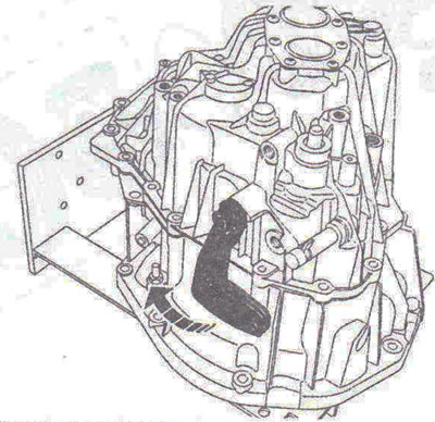
Figure 5.41. Rotate the shift lever to release the control lever, lifting the crankcase upward, and then remove the crankcase completely.
Caution! Save the adjusting washer A of the selector block (figure 5.42). It gets close to the block and can remain glued to the gearbox housing.
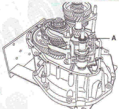
Figure 5.42. Save the adjusting washer A of the selector block. It gets close to the block and can remain glued to the gearbox housing.
9. Rotate the control unit, disengaging the spring at the top of the return sleeve, and remove the unit by pulling it upwards (figure 5.43).
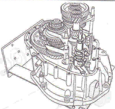
Figure 5.43. Rotate the control unit, disengaging the spring at the top of the return sleeve, and remove the unit by pulling it upwards.
10. Remove the axle and reverse clutch assembly B, then the 3rd/4th gear fork C (figure 5.44).
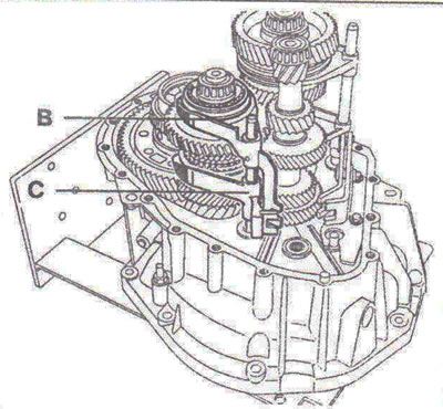
Figure 5.44. Remove the axle and reverse clutch assembly B, and then the 3rd/4th gear fork C.
11. Remove the 1st/2nd and 5th/6th gear synchronizers and the short secondary shaft (figure 5.45).
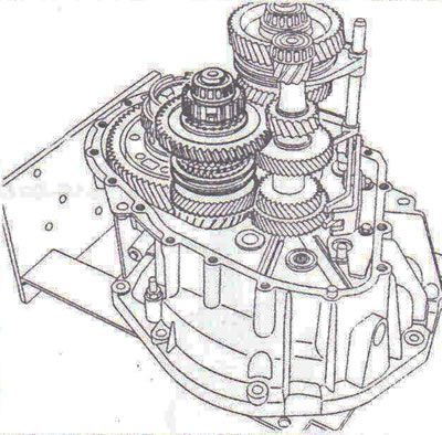
Figure 5.45. Remove the 1st/2nd and 5th/6th gear synchronizers and the short secondary shaft.
12. Remove the long secondary shaft assembly with the fork and the primary shaft (figure 5.46).
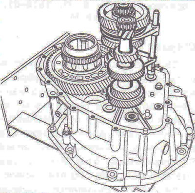
Figure 5.46. Remove the long secondary shaft assembly with the fork and the primary shaft.
13. Remove the gear (figure 5.47).
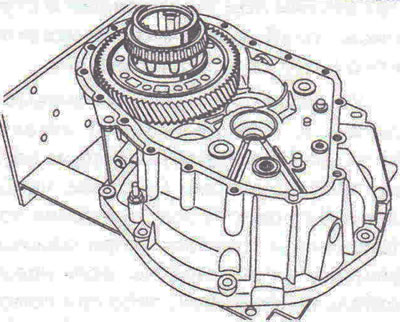
Figure 5.47. Remove the gear.
Removal gears (long secondary shaft)
14. Disconnect the snap ring (figure 5.48).
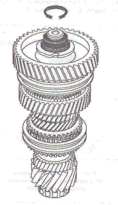
Figure 5.48. Disconnect the snap ring.
Note: To remove the snap ring, it is necessary to break the bearing separator.
15. Remove the ring-gear-clutch assembly using a press, using the puller to rest under the 2nd gear gear (figure 5.49).
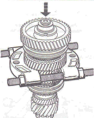
Figure 5.49. Remove the ring-gear-coupling assembly using a press, resting the puller under the 2nd gear.
16. Remove the ring-gear-clutch assembly using a press, placing device B. Vi. 1510-01, index L and a puller under the 6th or 5th gear gear, depending on the type of gearbox (figure 5.50).
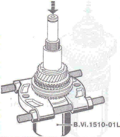
Figure 5.50. Remove the ring-gear-clutch assembly using a press, placing device B. Vi. 1510-01, index L, and a puller under the 6th or 5th gear gear, depending on the gearbox type.
17. Place a rag inside the device, at the bottom, to soften the fall of the shaft after it is removed.
Removal gears (short secondary shaft)
18. Disconnect the snap ring (figure 5.51).
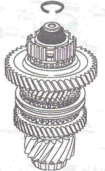
Figure 5.51. Disconnect the snap ring.
Note: To remove the snap ring, it is necessary to break the bearing separator.
19. Remove the ring-gear-clutch assembly using a press, placing device B. Vi. 1510, index L under the 3rd gear gear (figure 5.52).
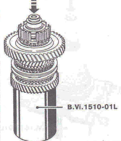
Figure 5.52. Remove the ring-gear-coupling assembly using a press, placing device B. Vi.1510, index L, under the 3rd gear gear.
20. Place a rag inside the device, at the bottom, to soften the fall of the shaft after it is removed.
Removal and installation bearings
21. Remove the bearings with a press using a puller (figure 5.53a, b).
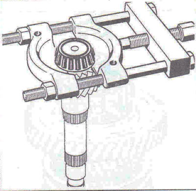
Figure 5.53a. Removing bearings on a long secondary shaft.
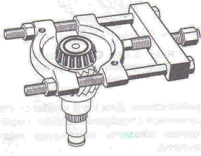
Figure 5.53b. Removing bearings on a short secondary shaft.
22. Install the bearings using tool B. Vi. 1510-01, index O (figure 5.54a, b).
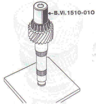
Figure 5.54a. Installing bearings on a long secondary shaft.
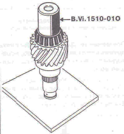
Figure 5.54b. Installing bearings on a short secondary shaft.
23. Remove the bearings with a press using a puller (figure 5.55)
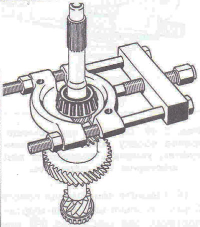
Figure 5.55. Remove the bearings with a press using a puller.
24. Install the bearings using tool B. Vi. 1510-01, index M (figure 5.56).
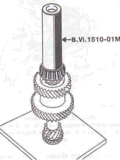
Figure 5.56. Install the bearings using device B. Vi. 1510-01, index M.
Assembly
25. The teeth of gears and couplings must not have any nicks and must not be excessively worn. Also make sure that the shaft surfaces and the inner surfaces of the gears are free from friction and excessive wear. It is recommended to mark the position of the toothed couplings in relation to the hubs. Bearings should be replaced whenever scratches or hot spots become visible, or if excessive wear occurs.
Installing gears
Caution: Replacing components such as gear bushings and hubs requires changing the installation order below.
26. Measure the height of the part being replaced and the part being installed. If the difference between the dimensions of two parts exceeds 0.025 mm, it is necessary to adjust the installation gasket. By increasing its thickness if the new part is lower than the old one, or by decreasing its thickness if the new part is higher than the old one.
Table 5.1 provides an example of calculating the value of a new installation gasket, which should be determined after replacing the bushings under the gears or hubs.
Table 5.1. Example of calculating the value of a new installation gasket, which should be determined after replacing the bushings under the gears or hubs
| Detail | Replaceable part | New detail | Difference |
| Replacing rings or hubs on a long secondary shaft | |||
| Bushing under the 6th gear pinion | a | A | - |
| Hub (5/6) | b | IN | - |
| Long 2nd gear ring | with | WITH | - |
| Hub (1/2) | d | D | - |
| Pad | x | X = x ±(a-A) ±(b-B) ±(c-C) ±(dD) | - |
| Replacing rings or hubs on a short secondary shaft | |||
| Bushing under the 4th gear pinion | a | A | - |
| Bushing under the reverse gear | b | IN | - |
| Hub (3-4) | with | WITH | - |
| Reverse hub | d | D | - |
| Pad | X | X = x ±(A-a) ±(B-b) ±(C-c) ±(D-d) | - |
Example: Replacing the bushing under the reverse gear of the short secondary shaft
| Detail | Replaceable part | New detail | Difference |
| Bushing under the 4th gear pinion | a | A | |
| Bushing under the reverse gear | B (30.802) | In (30.830) | |
| Hub (3-4) | with | WITH | + 0.028 |
| Reverse hub | d | D | |
| Gasket Result | 2.10 | X = x ±(A-a) ±(B-b) ±(C-c) ±(Dd) x = 2.10-0.028 = 2.028 |
Knowing that shim thicknesses range from 0.020 to 0.20, in this example you would select a shim with a thickness of 2.02.
Installing the Long Secondary Shaft Gears
27. Install needle bearing A, 6th gear gear B and its synchronizer ring (RK6 manual transmission) (figure 5.57). Using tool B. Vi. 1510-01, index N, fit the hub of the 6th/5th gear toothed clutch C (align the hub recesses with the synchronizer ring recesses so that they match). Using tool B. Vi. 1510-01, index N, fit the 5th gear D sleeve (ensure a pressure of 5 tons at the end of pressing).
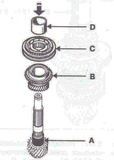
Figure 5.57. Install needle bearing A, 6th gear pinion B, 6th/5th gear clutch hub C, 5th gear pinion sleeve D.
28. Install the needle bearing E and the 5th gear pinion, as well as its synchronizer ring F (figure 5.58). Install the shaped washer G. Using the tool B. Vi. 1510-01, index N, fit the 2nd gear bushing H (ensure a pressure of 5 tons at the end of pressing).
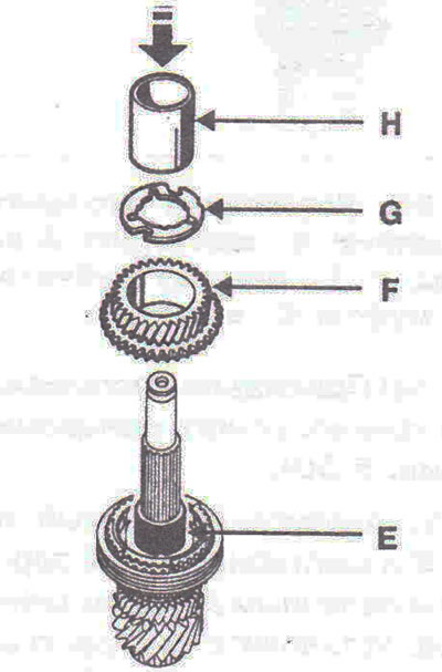
Figure 5.58. Install the needle bearing E, synchronizer ring F, shaped washer G, 2nd gear bushing H.
29. Install needle bearing I, 2nd gear J with three-cone synchronizer rings installed (figure 5.59).
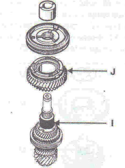
Figure 5.59. Install needle bearing I, 2nd gear J with three-cone synchronizer rings installed.
Caution! Position the three-cone synchronizer notches correctly (figure 5.60).
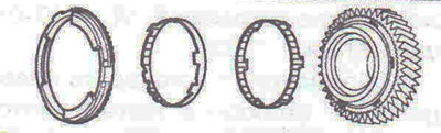
Figure 5.60. Correctly position the notches of the three-cone synchronizer.
30. Using tool B. Vi. 1510-01, index N, fit the hub of the 1st/2nd gear toothed clutch K, align the recesses of the hub with the recesses of the synchronizer ring so that they coincide (figure 5.61). Using the tool B. Vi. 1510-01, index N, fit the sleeve L of the 1st gear pinion (with the pin holes facing up) (ensure a pressure of 5 tons at the end of pressing).
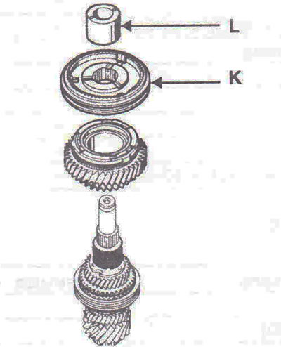
Figure 5.61. Install the hub of the 1st/2nd gear toothed clutch K, sleeve L.
Attention! The long flange of the hub is located on the 2nd gear side.
31. Install the needle bearing M, 1st gear gear N with the three-cone synchronizer rings installed on it (figure 5.62). Install a shaped washer with holes for pins O.
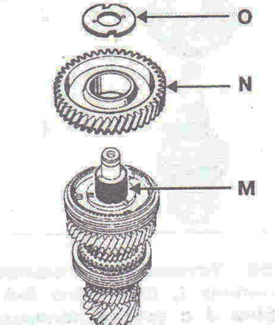
Figure 5.62. Install the needle bearing M, 1st gear gear N, and the shaped washer with holes for the pins O.
32. Fit the bearing using tool B. Vi. 1510-01, index O (figure 5.63).
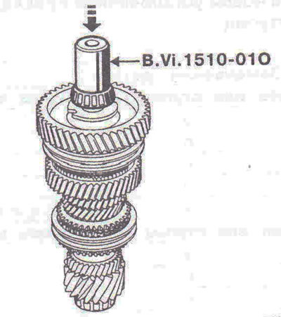
Figure 5.63. Mount the bearing using tool B.Vi. 1510-01, index O.
33. Select and install a new snap ring that will fit into the groove exactly (it should fit tightly into it).
Installing the short secondary shaft gears
34. Install needle bearing A, 3rd gear gear B with three-cone synchronizer rings installed (figure 5.64). Using tool B. Vi. 1510-01, index N, fit the hub of the toothed clutch C of the 3rd/4th gear. Using tool B. Vi. 1510-01, index N, fit the sleeve D of the 4th gear pinion (ensure a pressure of 5 tons at the end of pressing).
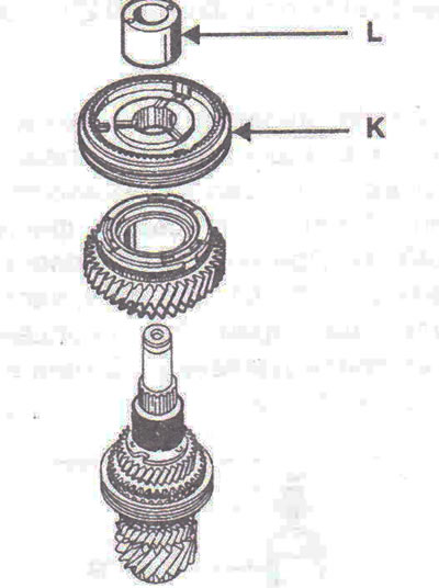
Figure 5.64. Install needle bearing A, 3rd gear gear B, toothed clutch hub C, sleeve D.
Caution! Position the three-cone synchronizer notches correctly (figure 5.60).
35. Install needle bearing E and 4th gear pinion (F) with synchronizer ring installed. Install the shaped washer G. Using the device B. Vi. 1510-01, index N, fit the sleeve H of the reverse gear (ensure a pressure of 5 tons at the end of pressing) (figure 5.65).
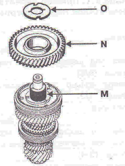
Figure 5.65. Install needle bearing E, shaped washer G, bushing H.
36. Install the needle bearing I, reverse gear J with the synchronizer ring installed (figure 5.66). Using tool B. Vi. 1510-01, index N, fit the hub of the reverse gear toothed clutch K.
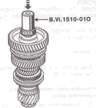
Figure 5.66. Install needle bearing I, reverse gear J, reverse clutch hub K.
37. Fit the bearing using tool B. Vi. 1510-01, index O (figure 5.67).
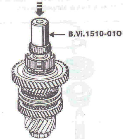
Figure 5.67. Mount the bearing using tool B.Vi. 1510-01, index O.
38. Select and install a new snap ring that will fit into the groove exactly (it should fit tightly into it).
Visitor comments