


Contents: Removal ⬇ Installation ⬇
Removal
1. Place the vehicle on a two-post lift.
2. Disconnect the battery.
3. Open the hood and remove the cabin ventilation filter housing A, air intake cover B (figure 5.11).
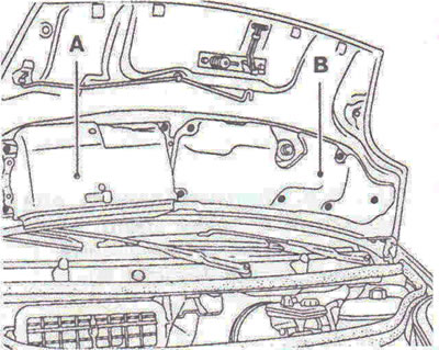
Figure 5.11. Open the hood and remove the cabin ventilation filter housing A and air intake cover B.
4. Disconnect the pipes from the charge air cooling radiator (figure 5.12).
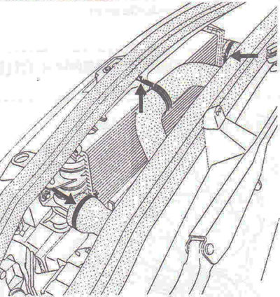
Figure 5.12. Disconnect the pipes from the charge air cooling radiator.
5. Remove the coolant preheater unit without disconnecting both hoses to release the flywheel side lifting bracket, the expansion tank from the bracket (without touching the tubes), secure the tank so that it can be moved (figure 5.13).
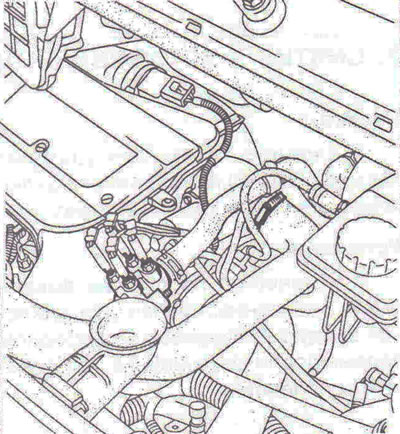
Figure 5.13. Remove the coolant preheater assembly without disconnecting both hoses to release the flywheel side lifting bracket.
6. Using a syringe, remove the brake fluid from the reservoir up to the nipple of the clutch master cylinder line.
7. Disconnect pipes E and F, wiring connectors G, H and I (figure 5.14).
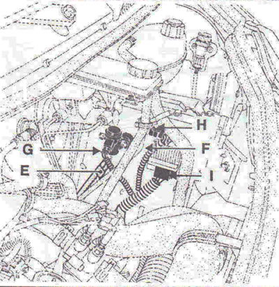
Figure 5.14. Disconnect tubes E and F, wiring connectors G, H and I.
8. Disconnect the air intake pipe of the filter.
9. Disconnect the pipe from the clutch slave cylinder 1 (figure 5.15). Disconnect breather tube 2.
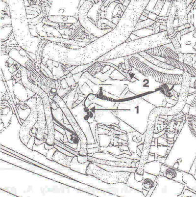
Figure 5.15. Disconnect the pipe from the clutch slave cylinder 1. Disconnect the breather pipe 2.
10. Remove the upper noise insulation cover of the gearbox, disconnect the wiring connector from the reverse light switch A, the gear selection and shift cables B (figure 5.16). Disconnect the two wire harnesses from the bracket on the C transmission.
11. Tie the wire harnesses to facilitate transmission removal.
12. Remove the front wheels, engine oil pan protection (central and front), gearbox noise insulation covers (lower and back parts) (figure 5.17).
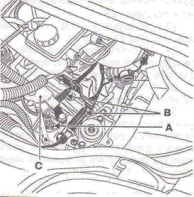
Figure 5.16. Disconnect the wiring connector from the reverse light switch A, the gear selector and shift cables B. Disconnect the two wiring harnesses from the bracket on the gearbox C.
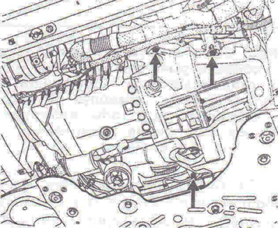
Figure 5.17. Remove the transmission noise insulation covers (lower and back parts).
13. Disconnect the wiring connectors from the electric fan of the engine cooling system.
14. Disconnect the radiator cross member by unscrewing bolt A and tilt the assembly forward, secure it to be able to remove the gearbox soundproofing casing (front part) (when carrying out work, the radiator/electric fan unit must remain on the crossbar) (figure 5.18).
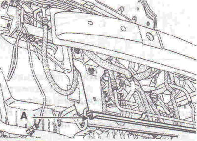
Figure 5.18. Disconnect the radiator cross member by unscrewing bolt A and tilt the assembly forward.
Note: This operation is performed on vehicles with air conditioning (for front noise insulation casing).
15. Drain the oil from the gearbox.
16. Remove the left and right side mudguard protective pads, the front brake calipers and tie them to the vehicle suspension springs so that the brake hoses are not loaded, disconnect the wires from the wheel speed sensors.
On the left side of the car
17. Unscrew the bolts securing the inner axle joint boot holder to the gearbox (figure 5.19).
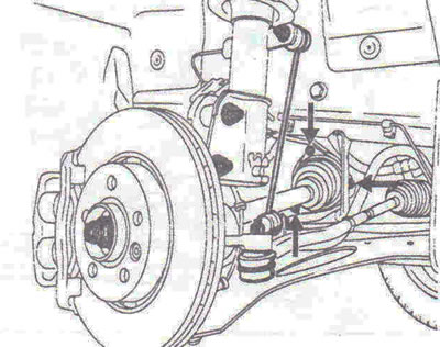
Figure 5.19. Unscrew the bolts securing the inner axle joint boot holder to the gearbox.
18. Disconnect the ball joints of the suspension arms. If the nut does not loosen, use an Allen key cut to size X. X = 25 mm.
19. Disconnect the ball joint of the steering rod end B using the T.Av.476 puller, unscrew the mounting bolts C of the shock absorber strut to the steering knuckle, remove the half shaft (figure 5.20).
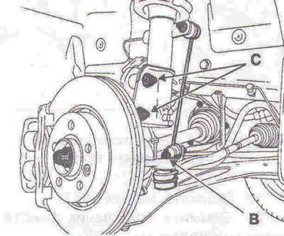
Figure 5.20. Disconnect the ball joint of the steering rod end B using the T.Av.476 puller, unscrew the mounting bolts C of the shock absorber strut to the steering knuckle, remove the axle shaft.
20. Take precautions to avoid damaging the anthers (figure 5.21).
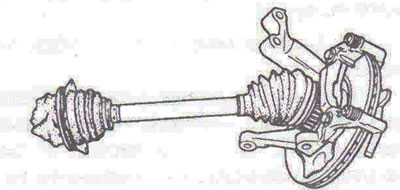
Figure 5.21. Take precautions to avoid damaging the anthers.
On the right side of the car
21. Unscrew the two bolts securing the intermediate support A and remove the intermediate support from the engine bracket (figure 5.22).
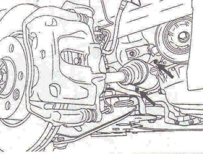
Figure 5.22. Unscrew the two bolts securing the intermediate support A and remove the intermediate support from the engine bracket.
22. Disconnect the ball joint of the suspension arm, the ball joint of the steering rod end, unscrew the bolts securing the shock absorber strut to the steering knuckle, remove the half shaft and the torque rod (figure 5.23).
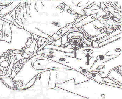
Figure 5.23. Disconnect the reaction rod.
23. Remove the TDC sensor.
24. Remove the subframe together with the suspension arms.
25. Loosen the rear mounting bolts of both subframe reinforcement rods.
26. Unscrew the nuts of the lower ball joints of the anti-roll bar struts, remove the steering gear cover, unscrew the bolts securing the steering gear to the subframe.
27. Place a hydraulic jack under the subframe.
28. Unscrew the two bolts of the front subframe mount, two bolts of the rear subframe mount.
29. Turn the subframe reinforcement rods outward.
30. Lower the subframe assembly with the suspension arms and anti-roll bar, turning the stabilizer bar to avoid it catching on the steering gear (figure 5.24).
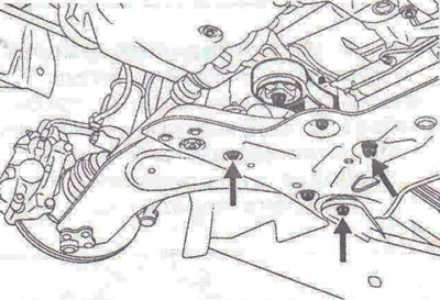
Figure 5.24. Lower the subframe assembly with the suspension arms and anti-roll bar, turning the anti-roll bar rod to avoid it catching on the steering gear.
31. Remove the front muffler (bolt A) and tie it to the body, disconnect the wiring connector from the speed sensor B, the ground wire of the wiring harness from the pre-catalyst bracket, pre-catalyst bracket C, the wiring connectors from the starter, unscrew the starter mounting bolts, remove the starter (pull it back and secure it), disconnect the air bleed pipe from the turbocharger D (figure 5.25).
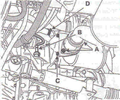
Figure 5.25. Remove the front muffler (bolt A) and tie it to the body, disconnect the wiring connector from the speed sensor B, the ground wire of the wiring harness from the pre-catalyst bracket, the pre-catalyst bracket C, disconnect the air bleed pipe from the turbocharger D.
32. Tie the wire harnesses to the body to facilitate removal of the transmission.
33. Secure the hood with a belt.
34. Fit the engine support crossbar Mot. 1453 and the tool Mot. 1453-01 (figure 5.26).
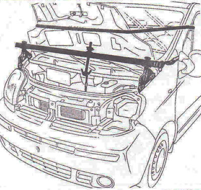
Figure 5.26. Fit the engine support crossbar Mot. 1453 and the Mot. 1453-01 tool.
35. Unscrew nut A, two bolts B securing the silent block, remove the silent block, unscrew the bolts securing the upper gearbox housing to the engine block, remove the gearbox support (figure 5.27).
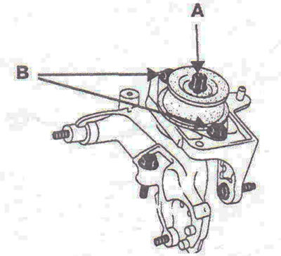
Figure 5.27. Unscrew nut A, two bolts B securing the silent block, remove the silent block, unscrew the bolts securing the upper gearbox housing to the engine block, and remove the gearbox support.
36. Tilt the power unit. Disconnect the hydraulic lines from the transmission support.
37. Remove the gearbox support.
38. Install the hydraulic jack.
39. Unscrew the bolts securing the lower gearbox housing to the engine and remove the gearbox.
Installation
40. Installation is carried out in the reverse order of removal.
Tightening torques
- Wheel mounting bolts - 142 Nm.
- Brake caliper guide pin mounting bolt - 35 Nm.
- Steering rod ball joint fastening nut - 37 Nm.
- Front suspension arm ball joint pin nut - 105 Nm.
- Bolt for fastening the shock absorber strut to the steering knuckle - 180 Nm.
- Hub nut - 280 Nm.
- Pendulum support mounting bolts to the body - 44 Nm.
- Bolts for fastening the pendulum support to the gearbox - 85 Nm.
- Front subframe mounting bolts - 105 Nm.
- Rear subframe mounting bolts - 120 Nm
- Rear subframe tie rod mounting bolts - 105 Nm.
- Bolt for fastening the reaction rod to the subframe - 180 Nm.
- Bolt for fastening the jet thrust to the engine - 105 Nm.
- Starter mounting bolts - 44 Nm.
- Gearbox housing to engine mounting bolts - 44 Nm.
- Filler plug - 4 Nm.
- Drain plug - 22 Nm.
Visitor comments