


The Bosch Motronic M.1.5.4 fuel injection system works as follows: a fuel pump immersed in the tank supplies fuel through a filter to the fuel line (rail). The fuel supply pressure is controlled by a regulator, which returns excess fuel to the tank.
Fuel is supplied through electronically controlled injectors, i.e. intermittently injected into the distribution line directly in front of the engine intake valves. The electronic engine control unit regulates the injection time and, thus, the amount of fuel injected. Fuel injection occurs sequentially: the injectors fire in turn in accordance with the ignition order.
Air is sucked in by the engine through the air filter, throttle valve and intake manifold and reaches the intake valves. The amount of incoming air is regulated by the throttle valve, which is controlled by the driver via the pedal and accelerator cable. The amount of incoming air is measured by an air flow meter. The air flow meter housing contains a thin heated plate, cooled by the passing mass of incoming air. The electronic control unit regulates the heating voltage of the plate so that the temperature of the plate, despite air cooling, remains constant. By changing the current passing through the plate, the control unit determines the engine load and accordingly regulates the volume of injected fuel.
Information received by the electronic control unit from other sensors, as well as commands sent to the actuators or control mechanisms, ensure optimal engine operation in any situation that arises while driving.
If one or more main sensors fail, the electronic control unit executes an emergency program to reduce the risk to the engine and ensure continued movement.
In such cases, the engine starts to run intermittently and may stall when you press the accelerator pedal.
Sensors and actuators of the injection system
- Coolant temperature sensor - informs the electronic control unit about the engine temperature.
- Air flow meter.
- The throttle position sensor transmits information about the angular position of the throttle valve to the electronic control unit.
- The idle speed controller determines the engine crankshaft speed at idle and ensures a constant speed regardless of the number of electrical consumers connected to the vehicle's electrical system, such as the rear window heater or air conditioning compressor.
- The fuel pressure regulator maintains a constant difference in fuel pressure between the fuel rail and the intake manifold.
- The manifold absolute pressure sensor determines the required volume of incoming air.
- The intake air temperature sensor, together with the manifold absolute pressure sensor, is used to determine the required volume of intake air.
- The camshaft position sensor transmits information to the control unit about the position of the piston of cylinder No. 1 at TDC.
- The crankshaft position sensor determines the rotation speed and position of the crankshaft during the compression stroke.
- Oxygen concentration sensor (lambda probe) regulates the composition of exhaust gases by determining the oxygen content in them and transmitting the corresponding information to the control unit.
- An accelerator pedal position sensor that tells the engine control unit the current position of the pedal; based on the signals received, the control unit sets the throttle valve opening angle.
- The knock sensor ensures engine operation with an increased compression ratio, while preventing detonation combustion of the air-fuel mixture. The sensor maintains the ignition timing at the detonation limit, which contributes to better use of the combustion energy of the air-fuel mixture and leads to reduced fuel consumption.
- Power steering sensor: When the power steering is turned on, the sensor sends a corresponding signal to the engine control unit.
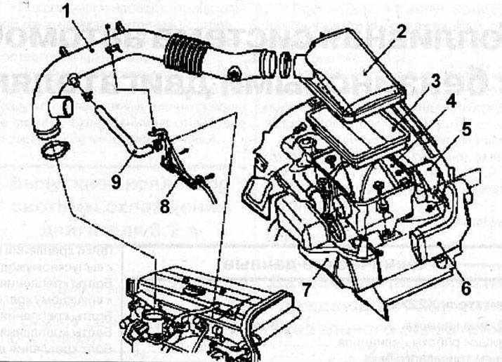
Air filter and air ducts for cars with 2.2L engines X22SE and Y22SE: 1 - air intake tube; 2 - air filter cover; 3 - air filter element; 4 - air filter housing; 5 - air intake tube; 6 - air intake tube; 7 - air intake tube; 8 - Air intake tube bracket; 9 - engine crankcase ventilation hose
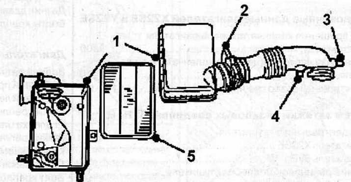
Air filter and air ducts for a car with a 3.2L engine (6VD1-W): 1 - air filter housing; 2 - air flow meter; 3 - connector; 4 - air temperature sensor connector; 5 - air filter element
When servicing the fuel system, carefully follow these cleanliness and safety precautions:
- Before servicing fuel system components, relieve the pressure in the fuel system as fuel may be released when the system is opened. Collect any leaked fuel with a rag. Wear safety glasses when performing work.
- Gasoline is extremely flammable, therefore, when working with fuel system components, the use of fire, sparking devices, open fire-hazardous lighting devices and smoking are prohibited. Avoid sparking when handling wires and electrical devices.
- Ensure good ventilation of the work area as fuel vapors are toxic.
- Thoroughly clean connection points and surrounding surfaces before disconnecting pipes.
- Prevent dirt from entering the fuel system. Place the removed parts on a clean surface and cover them with plastic wrap or paper. Do not use lint-free cloth for this purpose.
- Cover or seal exposed parts carefully if repairs are not to be made immediately.
- Remove spare parts from packaging immediately before installation.
- If possible, do not work with compressed air when the fuel system is open. Avoid moving the vehicle if possible.
- Do not use silicone based sealant.
Visitor comments