
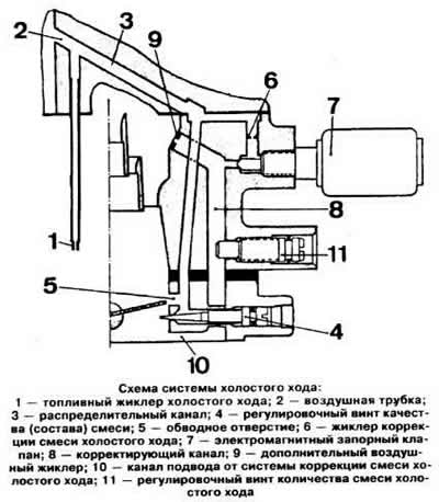
Idle mixture quantity correction system
Idle mixture correction system keeps the carbon monoxide content unchanged (SO) in exhaust gases, regardless of the amount of additional fuel-air emulsion.
The idle mixture flows through the idle mixture correction jet 6 (see picture) and an electromagnetic shut-off valve 7 and enters the correcting channel 8. where it receives an additional amount of air through the jet 9. The emulsion thus obtained is dosed by the adjusting screw for the amount of mixture 11 and enters the corrected mixture supply channel 10.
Adjusting screw 11 allows you to adjust the amount of idle mixture, i.e. determine the idle speed of the engine crankshaft.
Hot Engine Idling Air valve
The hot engine idle air valve is installed in the channel connecting the top of the float chamber to the 1st chamber. The valve opens and closes under the action of a bimetallic spring. When the engine is very hot, the valve opens and additional air enters the intake manifold.
This allows you to compensate at idle for the over-enriched combustible mixture caused by the vapor pressure generated during the evaporation of hot fuel in the float chamber.
At normal engine operating temperature, the valve is always closed. Therefore, before starting to adjust the engine idle speed, it is necessary to make sure that the hot engine idle air valve is closed.
Main dosing system of the 1st chamber
When the throttle valve of the 1st chamber is ajar, the vacuum in the intake manifold is quite large and. overcoming the resistance of the spring 3 (see picture), moves down the piston 1 together with the adjusting needle 2.
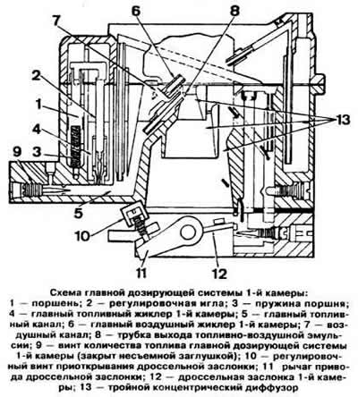
The amount of fuel coming from the opening of the main fuel jet is metered by the adjusting needle 2. From the outlet of the jet, the fuel enters the main fuel channel 5 and mixes with the air leaving the main air jet 6 of the 1st chamber and the flow channel 7. Through the tube 8, the fuel - air emulsion enters the carburetor diffuser.
When the throttle valve of the 1st chamber is fully open, the vacuum in the inlet pipeline drops and the spring 3 pulls the piston 1 up, removing the adjusting needle 2 from the main fuel jet 4 of the 1st chamber. As a result, the amount of fuel entering through the jet increases.
An additional amount of fuel enters the main fuel channel of the 1st chamber through an opening, the dimensions of which are determined by the position of the screw 9, which is adjusted at the factory. The screw is closed with a metal plug and there is no access to it.
Main dosing system 2nd chamber
Throttle valves of the 1st and 2nd chambers are mechanically interconnected. The 2nd chamber throttle starts to open when the 1st chamber throttle is already ⅔ of the way open (when the bimetallic spring of the automatic trigger is released), i.e. with a sharp acceleration and high speed engine operation.
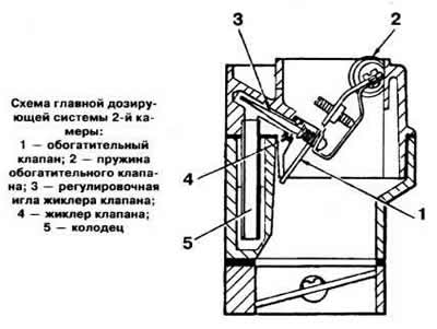
As the 2nd chamber throttle starts to open, the vacuum in the intake manifold tends to open enrichment valve 1 (see picture), which remains in the closed position under the action of spring 2. At a certain vacuum, the enrichment valve begins to open, moving the adjusting needle 3 of the valve jet 4. The fuel coming from the well 5 is sucked through the jet. The position of the adjusting screw of the metering needle of the jet is set at the factory and should not be changed during operation.
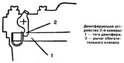
At the moment of opening the enrichment valve, a damping device comes into action, consisting of a pneumatic actuator, a rod and a lever, and acting independently of the starting device.
While the throttle valve of the 2nd chamber is closed, the diaphragm of the pneumatic drive is under the action of vacuum and through the rod 1 (see picture) keeps the enrichment valve in the closed position. When the throttle valve of the 2nd chamber is opened, the pressure in the pneumatic actuator drops and the diaphragm spring smoothly moves the rod 1, releasing the lever 2 of the enrichment valve, which opens.
Compensation system for the composition of the mixture of the 2nd chamber
The carburetor has a compensation system that provides a transition in its operation until the main dosing system of the 2nd chamber is turned on. Thus, excessive depletion of the combustible mixture is not allowed when the throttle valve of the 2nd chamber is opened. The mixture composition compensation system works as long as the throttle valve of the 2nd chamber remains open.
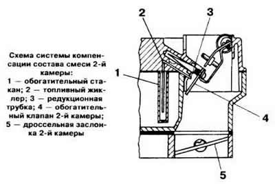
Fuel from the float chamber is taken through a calibrated hole into the enrichment cup 1 (see picture), from where, after the throttle valve of the 2nd chamber begins to open, it passes through the jet 2 built into the body of the carburetor and the reducing tube 3 and enters the space in front of the enrichment valve of the 2nd chamber.
Econostat
At full engine load at speeds close to the maximum, the econostat turns on. It provides an additional amount of fuel to the diffuser of the 1st chamber.

Under the action of vacuum supplied to the reducing tube 1 (see picture), fuel is taken from the float chamber through jet 2, at the outlet of which it is mixed with air entering through air jet 3. In addition, jet 3 is designed to control the amount of air-fuel emulsion during econostat operation.
Accelerator pump
The accelerator pump regulates the amount of combustible mixture when the throttle valve of the 1st chamber is sharply opened.
Lever 1 (see picture) the accelerator pump drive is connected by a rod to the throttle valve of the 1st chamber. When the damper is opened, the lever 1 presses on the piston 2 of the pump, which leads to a uniform injection of fuel through the ball valve 3 under the action of the spring 4.
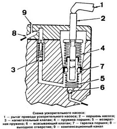
Then the return spring 5 moves the piston to its original position and the fuel again enters the pump cavity from the float chamber through the suction valve 6.
Visitor comments