


Contents: Checking the fuel level in the float…⬇ Adjusting engine idle speed ⬇ Adjusting the engine fast idle speed ⬇ Checking and adjusting the starting…⬇ Checking and adjusting the throttle…⬇ Adjusting the opening of the…⬇ Checking the tightness of the air…⬇ Checking and adjusting the…⬇
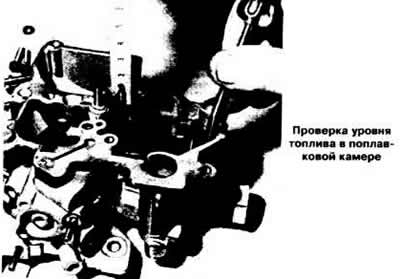
Checking the fuel level in the float chamber
The position of the float in the float chamber is not adjustable. If a malfunction is detected, check the tightness of the float and the condition of the needle valve, replace faulty parts.
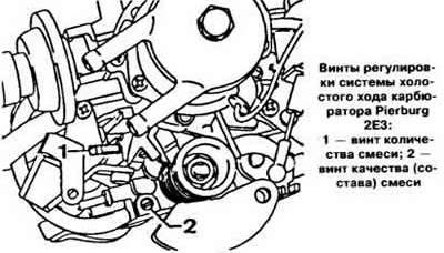
Adjusting engine idle speed
Before adjusting the engine idle speed, perform the following operations:
- make sure the air damper is fully open,
- warm up the engine. To do this, let the engine run at a crankshaft speed of about 2000 rpm until the thermostat opens. In no case should you warm up the engine at idle, since if the engine runs for several minutes at idle, the measurements of the carbon monoxide content in the exhaust gases will be distorted;
- check the cleanliness of the air filter element and replace it with a new one if necessary (when adjusting the engine idle speed, do not remove the air filter);
- check the functionality of the ignition system and the ignition timing,
- check for air leaks, paying particular attention to the connection of the vacuum hoses and the condition of the throttle body gasket;
- make sure there are no significant exhaust gas leaks in the exhaust tract;
- make sure that powerful current consumers (electric fan of the engine cooling system, headlights, rear window heating element, etc.) turned off.
Using the mixture quantity adjusting screw, set the crankshaft speed of the "13S" engine on cars with a manual transmission within 900-950 rpm, on cars with an automatic transmission 800-850 rpm, and the "16SV" engine within 900-950 and 800-850 rpm, respectively. The crankshaft speed of the "14NV" engine should be within 900-950 rpm.
Connect the gas analyzer according to the instructions.
Remove the plug of the mixture quality (composition) adjustment screw and, by turning it, achieve a CO content in the exhaust gases within 1.0-1.5% for the "13S" engine and 0.5-1.5% for the "16SV" and "14NV" engines.
If necessary, restore the specified engine crankshaft speed at idle using the mixture quantity adjusting screw.
Repeat these operations until the specified values of crankshaft speed and CO content are obtained.
After adjustment, replace the plug of the mixture quality (composition) adjustment screw.
Adjusting the engine fast idle speed
Adjustment of fast idle speed is performed on a warm engine (oil temperature not less than 70°C), with the ignition timing correctly set and idle speed adjusted.
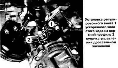
Install the adjusting screw 1 (see photo) of the fast idle speed on the second, upper, profile 2 of the throttle control cam.
Start the engine without pressing the accelerator pedal.
Check the crankshaft speed at fast idle, which for the "13S" engine on cars with a manual transmission should be within 2100-2500 rpm, on cars with an automatic transmission 2400-2800 rpm, for the "16SV" engine 2000-2400 and 2500-2900 rpm, respectively. The fast idle mode of the "14NV" engine should be within 2200-2600 rpm. If necessary, set the required fast idle mode of the engine with adjusting screw 1.
Checking and adjusting the starting clearance of the air damper
Remove the automatic starting device cover.
Close the choke and set the fast idle adjustment screw to the upper profile of the throttle control cam.
Disconnect the vacuum hose from the air damper pneumatic drive.
Connect the vacuum pump hose to the pneumatic drive fitting and use the pump to create a vacuum of approximately 0.3 kg/cm².
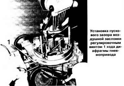
Raise the air damper drive lever. In this position, use a rod or drill to measure the air damper starting clearance, which should be within the limits specified in section "Design and technical characteristics". If necessary, use adjusting screw 1 (see photo) to set the required gap.
Disconnect the air pump from the air damper pneumatic drive and connect the vacuum hose to the pneumatic drive.
Replace the automatic starting device cover, aligning the marks on it and the carburetor body.
Checking and adjusting the throttle valve starting clearance
Remove the carburetor.
Install the adjusting screw 1 (see photo) of the fast idle on the upper profile of the throttle control cam. In this position, measure the starting clearance of the throttle valve with a rod or a drill, which should be 0.8 mm for the carburetor of the "16SV" engine on cars with a manual transmission and 1.25 mm on cars with an automatic transmission. For the carburetor of the "14NV" engine, the starting clearance of the throttle valve should be within 0.8-0.9 mm. If necessary, use the adjusting screw 1 to achieve the desired clearance.
Material provided by this website OPELBOOK
Install the carburetor, check and, if necessary, adjust the engine crankshaft speed at fast idle.
Adjusting the opening of the throttle valve of the 2nd chamber
The position of the throttle valve of the 2nd chamber is adjusted at the factory, but in case of a violation of the adjustment it can be restored on a previously removed carburetor as follows:
- fully open the throttle valve of the 1st chamber and fix it in this position by inserting a drill between the edge of the valve and the carburetor body;
- tighten the 2nd chamber throttle lock lever with a rubber band;
- unscrew the limit screw of the 2nd chamber throttle valve so that it moves away from the stop. Then screw in the limit screw so that it barely touches the stop,
- turn the limit screw another ¼ turn and lock it in this position;
- return the throttle valve of the 1st chamber to the closed position;
- install the carburetor.
Checking the tightness of the air damper pneumatic drive
Remove the air filter and disconnect the vacuum hoses from the air damper actuator.
Plug the lower outlet pipe of the pneumatic drive.
Connect the hose of the hand vacuum pump to the upper outlet pipe of the pneumatic drive and create a vacuum of 0.3 kg/cm³ in the pneumatic drive with the pump. If the vacuum does not remain unchanged, the pneumatic drive must be replaced.
Checking and adjusting the performance of the accelerator pump
Remove the carburetor.
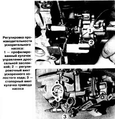
Turn the profiled cam 1 (see photo) of the throttle control so that the adjusting screw 2 of the fast idle speed moves away from it.
Place a graduated container with a funnel under the carburetor.
Slowly open and close the throttle valve of the first chamber ten times, thereby activating the accelerator pump (in this case, the fuel should come out of the pump nozzle each time for at least 3 seconds).
Determine the amount of fuel that has leaked into the vessel: for the carburetor of the "13S" engine it should be within 12.0-15.0 cm³, for the carburetor of the "16SV" engine model 90 107 522 — within 10.5-13.5 cm³, and for the model 90 107 523 — 7.5-13.5 cm³, for the carburetor of the "14NV" engine — 10.5-13.5 cm³. If the pump performance does not correspond to the given one, loosen the lock screw 3 and set the required performance by turning the pump drive cam. When turning the cam to the left, the pump performance increases and vice versa. After adjustment, tighten the lock screw 3 and lock it with a special varnish.
Visitor comments