
Main dosing system
Fuel for the formation of a combustible mixture is supplied through the main fuel jet 8 (see diagram), mounted at an angle to the flow at the bottom of the float chamber, air is supplied through a diffuser. The required amount of air in the combustible mixture is provided by a calibrated hole in the air jet 6 of the main metering system. The emulsion tube 7 is located at the outlet of the float chamber after the main fuel jet.
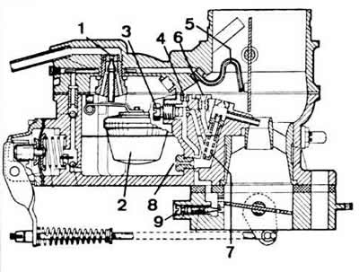
Solex 35 PDSI carburetor diagram
1 - needle valve;
2 - float;
3 - idle fuel jet;
4 - idle air jet;
5 - injection tube;
6 - main air jet;
7 - emulsion tube;
8 - main fuel jet;
9 - quality adjusting screw (composition) idle mixture.
Idle system
The fuel required to run the engine at idle is supplied by idle jet 3. The emulsifying air enters through idle air jet 4. The idle system has quantity and quality adjusting screws (composition) blends 9.
The accelerator pump serves to supply an additional amount of fuel during the acceleration of the car and works as follows. At idle, the throttle is closed. the diaphragm is held in place by a spring, allowing the float chamber to fill. The diaphragm is connected to the throttle actuator by means of a rod connected to the throttle valve axis. The rotation of the throttle axis when it is opened causes the diaphragm to simultaneously move, and fuel from the float chamber is injected into the diffuser through a calibrated atomizer.
Fuel mixture enricher
The fuel mixture enricher operates at full throttle. It consists of a calibrated vertical tube with a weight located in the float chamber and an enrichment tube located in a large diffuser. The end of the tube is located in the zone of reduced rarefaction of the diffuser. At low and medium engine load and crankshaft speed, the vacuum in the diffuser is not enough to lift a weight of 0.28 g and take fuel from a vertical tube. The weight is made in the form of a needle valve (see item 25 on the carburetor detail diagram).
With an increase in the crankshaft speed, the vacuum in the diffuser becomes sufficient to lift the weight and take fuel through the tube, as a result of which additional fuel begins to be supplied to the diffuser. The enrichment of the fuel mixture is gradually increased until the crankshaft speed reaches its maximum.
Starting device
The starting device provides starting and idling of a cold engine. The air damper is controlled manually from inside the car. Depending on the position, the damper can completely shut off the air supply to the main dosing system of the carburetor. A lever with a pin is attached to the end of the air damper axis, connected by a calibrated spring to the air damper drive cam.
The cam, located on the carburetor cover, is connected at one end to the choke cable, and through the other end to the fast idle lever, which is mounted on the throttle valve axis.
With the help of a latch made in the form of a spring-loaded ball and acting on the air damper lever, the air damper can be set to three fixed positions; the first two positions correspond to the full cover of the air damper and differ only in the degree of tension of the calibrated spring, and the third position corresponds to the full opening of the air damper.
To start a cold engine at low temperatures, pull the choke control fully out. As a result, the air damper will be completely closed, and the throttle will be ajar.
After running the engine for some time with the choke closed, the duration of which depends on the outside temperature, start to push the handle down a little until you feel the resistance of the choke ball in the intermediate position. At the same time, the tension of the spring holding the air damper in the closed position is weakened. which facilitates its opening under the influence of vacuum, while the throttle valve remains ajar. This ensures the optimal composition of the fuel-air mixture necessary for starting a cold engine and increasing the speed of the crankshaft during warm-up.
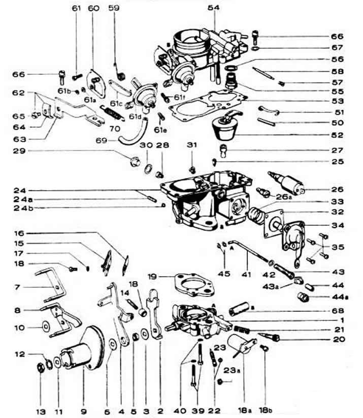
The main details of the Solex 35 PDSI carburetor:
1 - throttle body;
9 - throttle control drum;
14 - thrust screw;
19 - throttle body gasket;
20 - adjusting screw for the amount of idle mixture;
22 - quality adjusting screw (composition) idle mixtures;
23 - gasket;
23a - plug quality adjusting screw (composition) mixtures;
24 - carburetor body;
25 - needle valve of the combustible mixture enricher;
26 - electromagnetic shut-off valve;
26a - idle fuel jet;
27 - seat of the needle valve of the combustible mixture enricher;
28 - main fuel jet;
29 - cork;
31 - main air jet;
32 - accelerator pump diaphragm;
41 — thrust drive accelerator pump;
50 - axis of the float;
52 - float;
53 - carburetor cover gasket;
54 - carburetor cover;
55 - needle valve;
56 - sealing ring;
61 d - air damper pneumatic actuator.
Visitor comments