
Disassembly
Remove the cylinder head and place its mating surface on two pieces of wood.
Remove the fuel injection line.
Remove the distributor cap with gasket.
Remove the ignition distributor rotor.
Remove the ignition distributor housing.
Disconnect wires and remove spark plugs.
Loosen the camshaft bearing cap nuts evenly. loosening the nuts no more than one turn so that the camshafts remain parallel to the bearings when the valve springs are released.
Remove bearing caps and camshafts.
Place a box next to the workplace for laying hydraulic pushers, valves and valve springs in the order of their installation.
Using a suction cup, remove the valve lifters.
Warning. Lay the removed pushers in the working position, i.e. the annular recess of the skirt down to prevent oil from pouring out of them. Hydropushers are non-separable.
Place the alignment marks on the valve heads.
Compress the valve springs using a special tool, such as KM 653.
Remove the valve cotters with a magnetized screwdriver. Lightly tap the valve spring compressor to loosen the stuck nut.
Remove valve springs, spring plates, valves, valve stem seals and spring washers.
Warning. If sodium-cooled exhaust valves are discarded, they must be placed in a designated area due to the risk of environmental contamination.
Clean the valves, remove carbon deposits from them, being careful not to damage the working chamfers.
Degrease camshafts, poppet cotters and valve spring washers.
Wipe the pushers.
Clean the combustion chambers and cylinder head passages from carbon deposits, protecting the valve seats and the mating surface of the cylinder head from damage.
Degrease the housings and bearing caps of the camshafts, valve guides. lubrication channels with petroleum ether or trichlorethylene and dry them with compressed air.
Check the degree of wear of the guide bushings, new seats. condition of the mating surface with the cylinder block.
Assembly
Reinstall the valves, lubricating their rods with engine oil.
Install the valve spring support washers, after applying grease to the washers.
Put on the annular grooves of the valve stems the protective caps supplied with the new oil seals.
Using a KM 663 tool, install new oil seals, carefully pressing them all the way onto the guide bushings with light hammer blows.
Using a magnetized screwdriver, install the valve cotters.
Install valve lifters. Apply a layer of grease based on molybdenum disulphide to the ends of the pushers.
Install the camshafts.
Apply a layer of sealant (e.g. No. 15 04 700 (8 983 368) or Loctite 572) on the outer edges of the camshaft bearing caps. Install the covers according to the numerical markings.
Tighten evenly ½ of the bearing cap stud nuts to ensure simultaneous compression of the valve springs, after which, finally tighten the bearing cap stud nuts to a torque of 2.0 kgf·m, except for the nuts of the bearing cap fastening studs No. 11, which must be tightened to a torque of 1.0 kgf·m.
Turn the camshafts with a spanner wrench. so that the pulley pins are facing up.
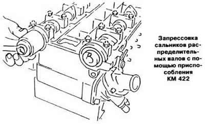
Press in new camshaft seals using tool KM 422 (see picture).
In the future, the assembly of the cylinder head is carried out in the reverse order of removal. In this case, it is necessary to install a new gasket for the ignition distributor cover.
Visitor comments