
Place the crankshaft in the main bearings.
Check the clearance between the liners and the crankshaft journals using a calibrated plastic wire.
Thoroughly clean the working surfaces of the inserts and the corresponding neck and place a piece of plastic wire on its surface.
Depending on the type of the checked neck, install a connecting rod with a cap or a main bearing cap on the neck and tighten the nuts or fastening bolts, as indicated in subsection «Design and specifications».
Remove the cover and, using the scale printed on the package, determine the size of the gap by the flattening of the wire (see values in subsection «Design and specifications»).
If the gap is less than the limit, then these liners can be used again. If the gap is greater than the limit, the liners on these necks must be replaced with new ones. If the crankshaft journals are worn and are ground to oversize, liners of the appropriate oversize must be fitted.
Determine the axial movement of the crankshaft, which is limited by liners with thrust collars on the middle support. Check the axial clearance between the thrust collars of the bearing shells and the thrust surfaces of the crankshaft as follows:
- install the indicator on a magnetic stand on the toe of the crankshaft and insert the end of the screwdriver, as shown in the photo;
- move the shaft with a screwdriver and check the axial clearance on the indicator (see values in subsection «Design and specifications»).
If the clearance is greater than the allowable, grind the crank webs and main journals to the oversize and install the bushings with thrust collars and the remaining main bearing shells of the appropriate oversize.
Install the liners in the block bed and in the crankshaft main bearing caps, having previously lubricated the inner surfaces of the liners with engine oil. Lubricate the bearing surfaces of the rear main bearing cap with sealant and place a bead of sealant with a diameter of about 6 mm into the grooves of the cap (shown by the arrow in the photo). Tighten the bolts of the main bearing caps, as indicated in the subsection «Design and specifications».
Note. Align the front main bearing cap before tightening the bolts.
After making sure that the crankshaft rotates freely and that there are no jams, install the flywheel and tighten the bolts of its fastening to the specified moment, having previously lubricated them with a locking compound.
Using a mandrel, press the piston pin out of the connecting rod without heating. The piston pin cannot be reused.
Select pistons in accordance with the size group of cylinders and in compliance with mounting clearances (see subsection «Design and specifications»).
Heat the connecting rod to a temperature of 280°C in an electric furnace or on a heating plate with a power of 1500-2000 W, controlling the heating temperature with a thermochromic pencil.
Put a conductor (KM 427 for engines «13N», «13S», KM 337 for engines «16S», «18E», «18SE», KM 634-6 for engines «14NV», «16SV», «C16N2», KM 634-3 for other engines) and mandrel into a new piston pin lubricated with engine oil, and push the pin into the piston bore.
Quickly clamp the heated connecting rod in a vise.
Orient the piston relative to the connecting rod, as shown in the photo.
When connecting a new piston to a connecting rod, observe the assembly dimensions (see subsection «Design and specifications»).
Quickly push the piston pin into the connecting rod bore until the mandrel shoulder rests against the piston skirt.
Note. To properly connect the pin to the connecting rod, press the pin as soon as possible, since the connecting rod cools quickly, and after cooling it will not be possible to change the position of the pin without deforming it.
Using a piston ring opener, install the piston rings into the grooves; check the gaps in the locks and position the locks of the rings through 180°. In this case, the locks of the upper and lower disks of the oil scraper ring should be located at a distance of 25-50 mm, respectively, to the left and right of the lock expanders.
Using a piston ring compressor, install the piston and connecting rod into the cylinder.
Install new connecting rod cap bolts and tighten them as indicated in subsection «Design and specifications».
Warning. Connecting rods without bearing shells should differ from each other in mass by no more than 8 g. When replacing a connecting rod, it is necessary to weigh it and install a new connecting rod of exactly the same mass.
Install the cylinder head and camshaft bearing housing as above.
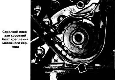
Install the oil pump and oil sump.
Warning. The short oil sump bolt is placed on the timing gear drive side, as shown in the photo.
Install water pump if removed.
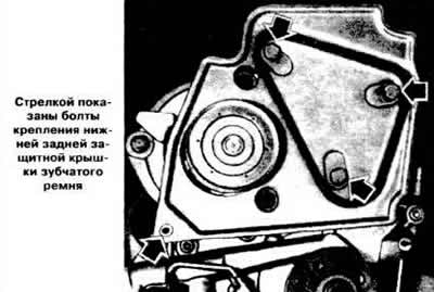
Reinstall the bottom rear toothed belt guard (see photo).
Put the camshaft drive belt on the pulleys, then install the crankshaft pulley.
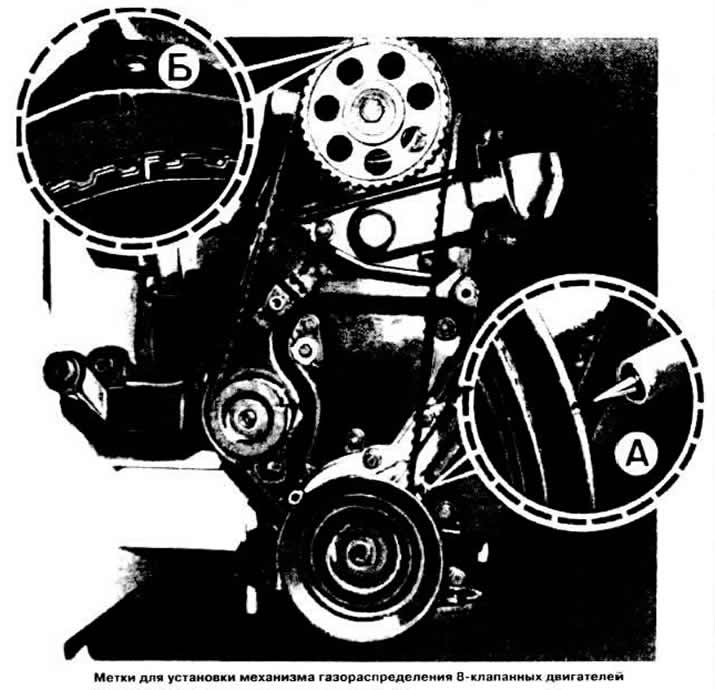
Rotate the crankshaft until the mark on the crankshaft sprocket aligns with the alignment lug on the cylinder block and the mark on the camshaft sprocket aligns with the mark on the top rear toothed belt guard (see photo) or marked on the camshaft bearing housing.
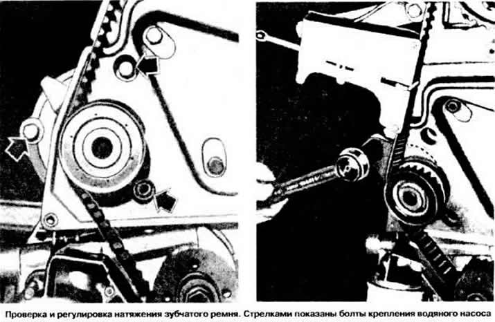
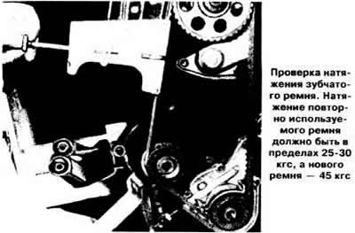
Adjust the timing belt tension by turning the water pump housing (see photo), by checking the belt tension with a special tool.
Note. The installation of the timing mechanism drive of a 16-valve engine is described in the corresponding subsection, see above.
Install the front toothed belt guard.
Install the generator, put its drive belt on the pulleys.
Visitor comments