


Contents: Lubrication system (1.4L engines) ⬇ Lubrication system (1.6L engines) ⬇ Lubrication system (1.8L engines) ⬇
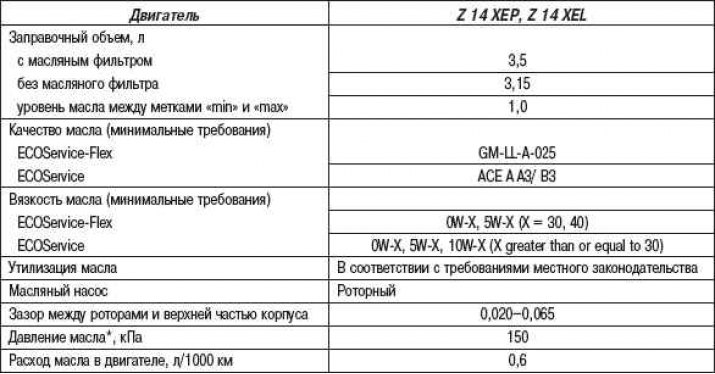
Lubrication system (1.4L engines)
Lubrication system (1.6L engines)
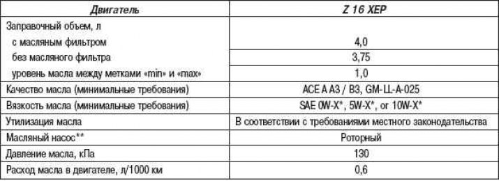
* "x" is greater than or equal to 30.
** the engine is warm and idling.
Lubrication system (1.8L engines)
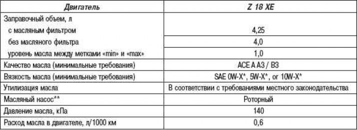
* "x" is greater than or equal to 30.
** the engine is warm and idling.
Removal
Before the inspection procedure, warm up the engine to operating temperature (oil temperature – 80°C).
Open the hood.
Loosen the fastening nut and disconnect the ground wire from the battery
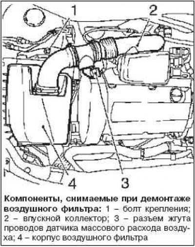
Remove the air filter housing and intake manifold.
Disconnect the MAF sensor wiring harness connector.
Loosen the mounting bolt, remove the clamp and the air filter inlet pipe.
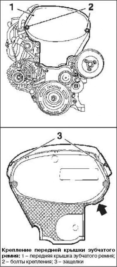
Remove the two mounting bolts, detach the upper latch and remove the front timing belt cover (top).
Note: Pull the front timing belt cover upwards by the lug (arrow in the picture).
Remove the ignition module cover in the direction of the arrow shown on it.
Note: Mark the position of the arrow on the cover.
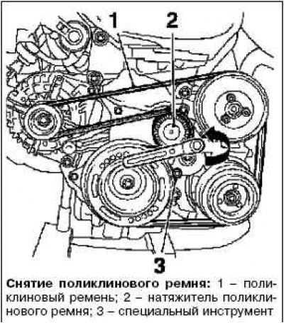
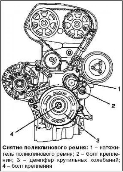
Remove the poly V-belt.
Mark the direction of rotation.
Squeeze the poly V-belt tensioner in the direction of the arrow in the figure and secure it using the special tool KM 6130.
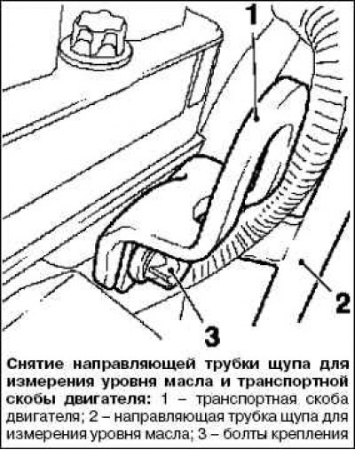
Remove the oil dipstick guide tube.
Remove the dipstick.
Loosen the mounting bolts.
Remove the engine transport bracket.
Raise the car.
Remove the engine splash shield.
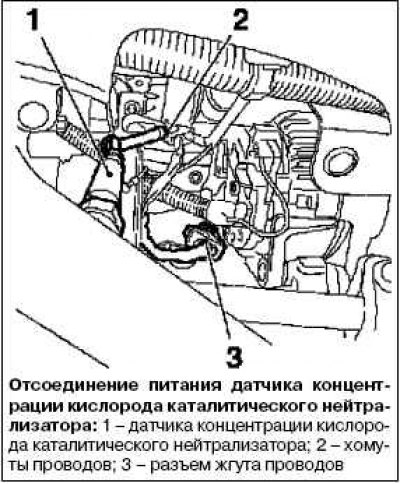
Remove the catalytic converter oxygen sensor wiring harness.
Remove the wire clamps.
Disconnect the wiring harness connector.
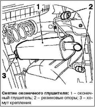

Remove the final muffler.
Loosen the mounting clamp.
Loosen the mounting nut and remove the muffler from the bracket.
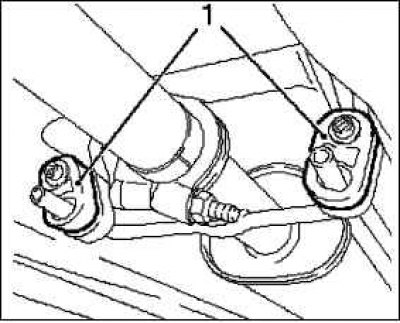
Disconnect the 2 rubber mounts and remove the tail pipe from the front muffler.
Disconnect the front exhaust pipe (2) from the catalytic converter by unscrewing the 3 mounting nuts.
Remove the front exhaust pipe from the front muffler by disconnecting the 2 rubber supports (1).
Place a container underneath to collect the liquid.
Drain the engine oil.
Disconnect the oil level sensor wiring harness connector.
Remove the oil pan.
Remove 2 rubber plugs.
Remove the 3 gearbox mounting bolts.
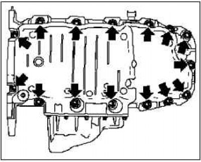
Unscrew 15 mounting bolts (arrows).
Remove the oil pan using a suitable tool.
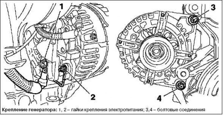
Disconnect the alternator from the electrical power supply by unscrewing the 2 mounting nuts.
Disconnect 2 bolt connections.
Remove the alternator.
Remove the plugs.
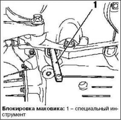
Insert the special tool KM 911 and lock the flywheel.
Remove the vibration damper by unscrewing the mounting bolt.
Remove the poly V-belt tensioner by unscrewing the mounting bolt.
The poly V-belt tensioner is locked using a special tool KM 6130.
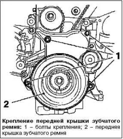
Remove the front timing belt cover (bottom) by unscrewing the 4 mounting bolts.
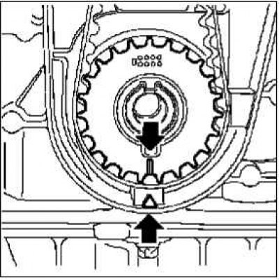
Set the engine to TDC.
Remove the special tool KM 911.
Tighten the vibration damper bolt.
Rotate the engine crankshaft in the direction of rotation to set the piston of cylinder No.1 to the top dead center (TDC) position (arrow).
Insert special tool KM-6173.
Attach KM-6001-A.
Note: Using the KM-6001-A ensures alignment of the drive with the front axle housing.
Loosen the 3 bolts (arrows) in the adjusting rails.
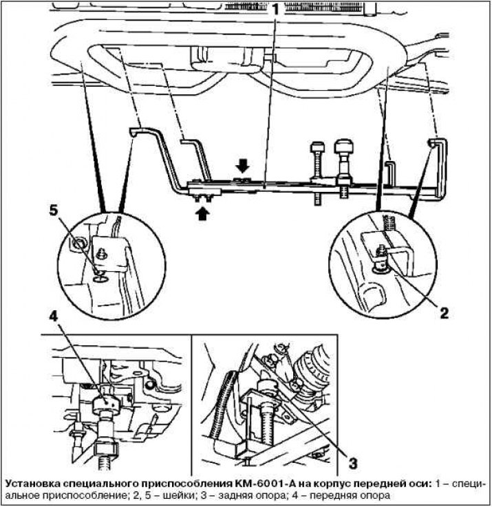
Insert special tool KM-6001-A.
The journals must be located in the holes in the front axle housing guide.
Tighten the 3 mounting bolts into the adjusting rails.
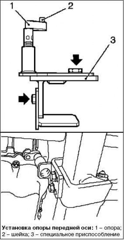
Adjust the supports and raise them to the stops on the guide journals.
Tighten the 3 adjusting tie bolts.
Adjust the supports - front and rear.
Raise the supports to the limiter on the guide necks.
Note: The guide journals must be positioned on the supports without any gap.
Lower the car
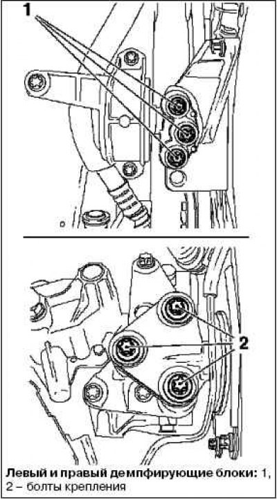
Remove the engine damper block with the right damper block adapter by unscrewing the 6 mounting bolts.
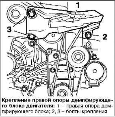
Remove the right support of the engine damping block, unscrew the 3 mounting bolts.
Install the camshaft gears using the special tool KM 6340.
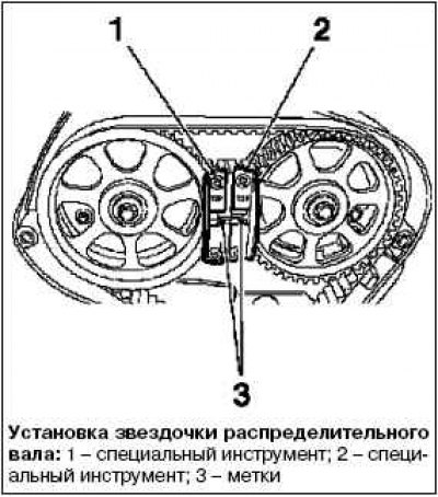
Install the camshaft sprockets so that the marks (3) are located opposite each other.
Install special tool KM-6340-left on the intake camshaft sprocket (I).
Install special tool KM-6340-right.
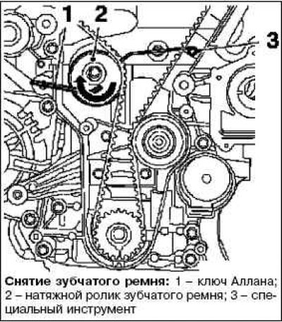
Remove the timing belt and mark the direction of rotation.
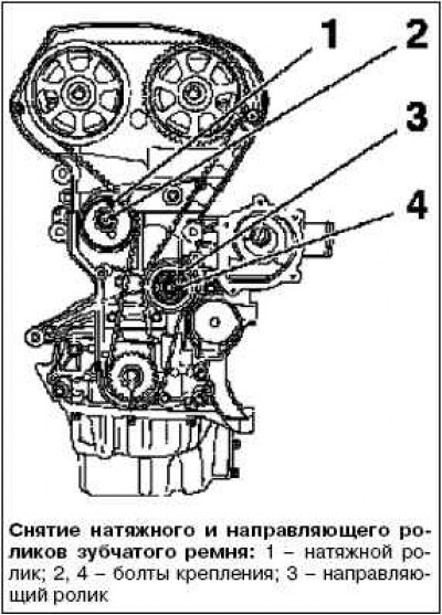
Apply force to the timing belt tension roller in the direction of the arrow using the Allan key. Secure with the special tool KM 6333.
Remove the timing belt tensioner and guide rollers.
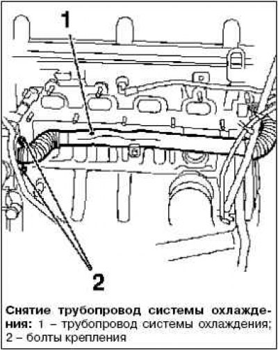
Remove the cooling system pipe by unscrewing the 2 mounting bolts.
Remove the pump module by unscrewing the 8 mounting bolts.
Note: Bolts are different lengths.
Remove the crankshaft oil seal (front) with a suitable tool.
Examination
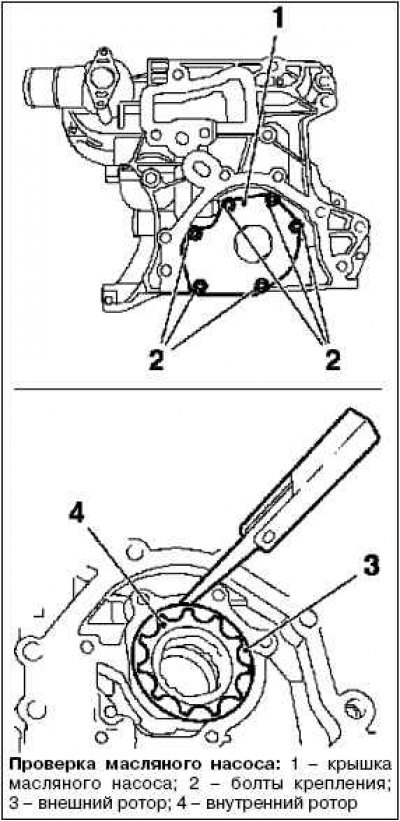
Check the distance between the outer rotor and the pump module.
Remove the oil pump cover.
Check the distance between the outer rotor and the oil pump housing.
Remove the outer rotor with the inner rotor.
Visually inspect the components.
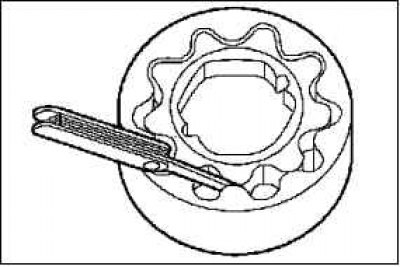
Original source is on the website (Opelbook.ru)
Measure the gap between the inner and outer rotor.
Installation
Install the oil pump cover.
Tighten the 6 mounting bolts to 8 Nm.
Install the pump module.
Note: Screws are different lengths.
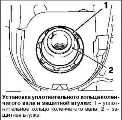
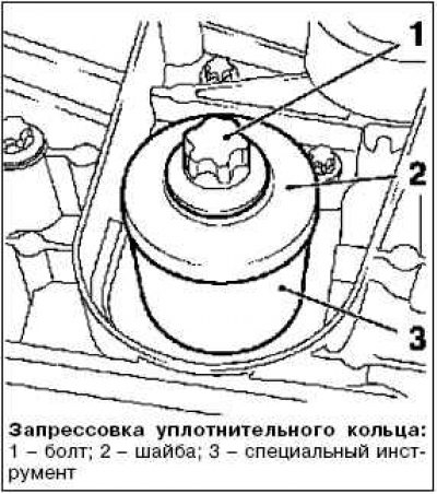
Tighten the 8 mounting bolts to 20 Nm.
Insert the front crankshaft seal ring.
Clean the surfaces to be sealed.
Apply silicone grease (white) to the sealing edge.
Install the protective sleeve onto the crankshaft journal.
Place the sealing ring by sliding it along the protective sleeve onto the crankshaft journal.
Press the sealing ring into the crankshaft.
Remove the protective sleeve and press the sealing ring into the pump housing using the special tool KM 6351.
Use the crankshaft pinion bolt and washer.
The installation of the remaining components is carried out in the reverse order of removal.
Visitor comments