
Engines 1.0 and 1.2 l
Removing
1. Turn out bolts of fastening and remove a protective casing (2) cylinder head cover in the direction indicated by the arrow in the illustration.
Removing the protective cover
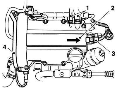
2. Disconnect the wiring connector (4), disconnect the PCV hoses (1) from the cylinder head cover and disconnect the multi-pin electrical wiring connector (3) ignition module (refer to illustration).
3. Turn out bolts of fastening of the module of ignition.
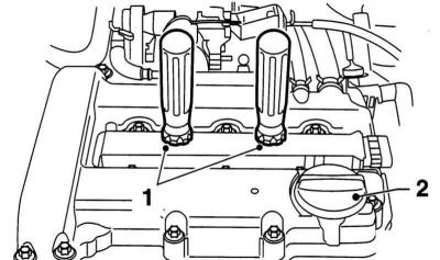
4. Remove the ignition module upward from the cylinder head. To do this, screw a special gripper KM-574 into the module (1). If there is no grip, screw in the appropriate bolts and pull the ignition module out by the bolts. Remove the oil filler cap (2).
Removing the ignition module and oil filler cap
5. Unscrew the cylinder head cover bolts evenly in several stages.
Bolts of fastening of a cover of a head of cylinders
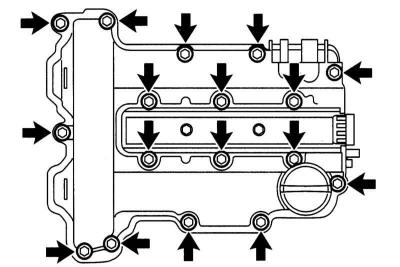
6. On the engine DOHC 1.2L the cylinder head cover is additionally secured with four bolts.
7. Remove the cylinder head cover.
8. Remove the cylinder head cover gasket and clean the mating surfaces.
Installation
1. Insert a new seal into the cylinder head cover.
2. Apply sealant to mating surfaces.
Sealing locations
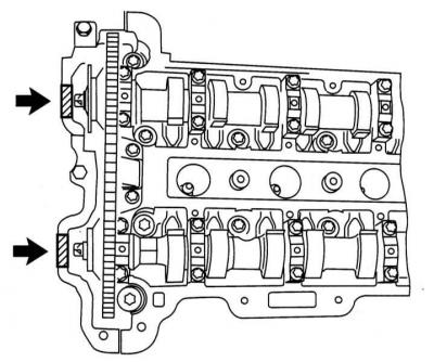
3. Install the cylinder head cover with a new seal and evenly tighten the mounting bolts in several stages with force 8 Nm.
4. Install the oil filler cap.
5. Install the ignition module on the spark plugs and tighten the bolts of its fastening with force 8 Nm.
6. Further installation is carried out in the reverse order to the dismantling of the components.
Engines 1.4 and 1.6 l
Removing
1. Release fuel pressure (see chapter Power supply systems, release and reduction of toxicity of exhaust gases).
2. Disconnect the negative cable from the battery.
3. Remove the air filter with MAF sensor and air intake sleeve (see chapter Power supply systems, release and reduction of toxicity of exhaust gases).
4. Drain the coolant into a prepared container (see chapter Engine cooling, interior heating and air conditioning systems).
5. Disconnect the upper and lower radiator hoses (see chapter Engine cooling, interior heating and air conditioning systems).
6. Turn out bolts of fastening and remove the tank from a bulkhead of an impellent compartment.
7. Remove the BB wire cover.
8. Disconnect the fuel supply hose (1) from the fuel line and fuel return hose (2) from the fuel pressure regulator. Pre-mark the fuel hoses with tape so as not to mix them up during installation. Clamp the hoses with clamps.
fuel hoses
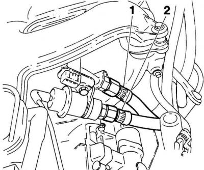
Place a rag under the leaking fuel.
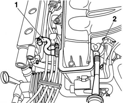
9. Disconnect the PCV hose (1) and brake booster vacuum hose (2) from the top of the intake manifold.
PCV hose and brake booster hose
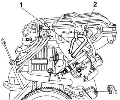
10. Disconnect the vacuum hose from the fuel pressure regulator (1) and from the evaporator control valve (2) on top of the intake manifold. The accompanying illustration shows the C16XE engine. On other engines, additionally disconnect the vacuum hose of the pressure sensor in the intake manifold (MAP).
Vacuum hoses for fuel pressure regulator and intake manifold
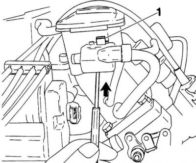
11. On C16XE engine loosen the clamp with a screwdriver (1) evaporator control valve (arrow) and remove it together with the valve upwards from the holder. Set aside the evaporator control valve.
Removing the Evaporator Check Valve
12. Remove the throttle cable from the throttle body and move the cable to the side (see chapter Power supply systems, release and reduction of toxicity of exhaust gases).
13. Disconnect the DIS ignition module multi-pin connector and disconnect the electrical wiring from the temperature sensor on the thermostat housing.
14. Disconnect the air injection pipe from the throttle valve.
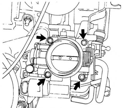
15. Turn out bolts of fastening of a branch pipe of a butterfly valve (arrow). Remove the tube and set it aside.
Throttle valve mounting bolts
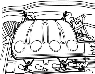
16. Give bolts of fastening of the top part of the inlet pipeline.
Bolts of fastening of the top part of the inlet pipeline
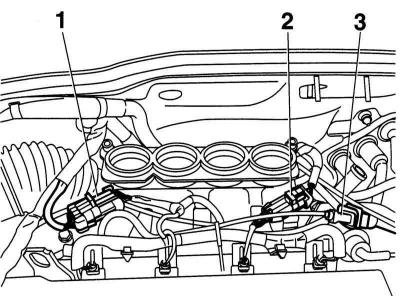
17. Disconnect the CKP sensor connector (2) and CMP sensor (3). On C16XE engine disconnect the injector connector (1).
Connectors for sensors and injectors
18. Disconnect the negative wire from the bottom of the intake manifold.
19. Disconnect the vacuum hose from the fuel pressure regulator.
20. Disconnect the PCV hose from the cylinder head cover.
21. On X14XE and X16XE engines remove the auxiliary air pump from the engine along with the wiring (see chapter Power supply systems, release and reduction of toxicity of exhaust gases).
22. Give 10 timing cover bolts and remove the cover together with the sealing elements.
Installation
1. Make sure that the mating surfaces of the cap and head are clean and dry.
2. Install new gaskets on the cylinder head (1) and new o-rings (2).
Timing cover seal elements
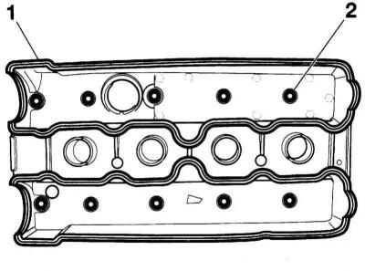
To prevent the O-rings from falling into the cylinder head during installation, lubricate them with a small amount of Vaseline. Lubricate the corners of the camshaft bearing cap on the side of the camshaft pulleys with OPEL L000 0295 sealant.
3. Carefully place the timing cover in its regular place, controlling the correct placement of the seals. Screw in the mounting bolts and, moving in a spiral from the center to the edges, evenly tighten them with force 8 Nm.
4. Establish the top part of the inlet pipeline and tighten bolts of its fastening with effort 8 Nm.
5. Install the throttle valve pipe with a new seal and tighten the bolts of its fastening to the top of the inlet pipeline with a force 8 Nm.
6. Install the throttle cable to the throttle body and check its adjustment (see chapter Power supply systems, release and reduction of toxicity of exhaust gases).
7. Further installation is carried out in the reverse order to the dismantling of the components.
Visitor comments