
Start work only after the engine has completely cooled down!
Removing
Engines 1.4 and 1.6 l
1. Remove the timing cover (see Section Removal and installation of a cover of the gas-distributing mechanism).
2. Separate a socket of a lambda probe and remove it from the holder on a transmission.
3. Turn out bolts of fastening and disconnect a reception pipe at a final collector and at a connecting flange to the catalytic converter.
4. Remove the starter (see chapter Engine Electrical Systems).
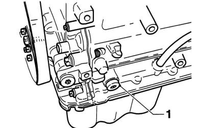
5. Give two bolts of fastening of the pulse gauge near a gear wheel of a camshaft.
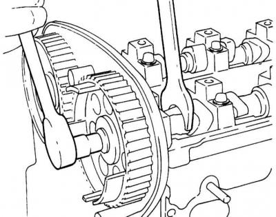
6. Turn out bolts of fastening of cogwheels of camshafts for what hold shafts from turning a wrench for inflow of the first cylinder.
Holding the camshafts when removing the gear bolts
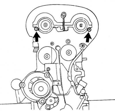
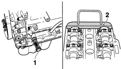
7. Turn out the top bolts of fastening of a back cover of a gear belt.
Top bolts of fastening of a back cover of a gear belt
8. Turn out bolts of fastening and remove both intermediate roller of a gear belt from a head of cylinders.
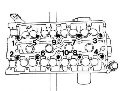
9. Loosen all cylinder head bolts in the order indicated in the accompanying illustration.
The order of giving the fasteners of the cylinder head
The cylinder head bolts may only be loosened when the engine is cold.
10. Remove the cylinder head with intake manifold and exhaust manifold.
Engines 1.0 and 1.2 l
The following describes the removal and installation of the cylinder head of the 1.0L DOHC three-cylinder engine. For the DOHC 1.2L four-cylinder engine, proceed in the same way. Special instructions are given in the appropriate places.
1. Release fuel pressure (see chapter Power supply systems, release and reduction of toxicity of exhaust gases).
2. Disconnect the negative cable from the battery.
3. Remove the air filter with MAF sensor, air intake sleeve and crankcase ventilation hose (PCV).
4. Drain the engine oil (see chapter Vehicle settings and routine maintenance).
5. Drain the coolant (see chapter Vehicle settings and routine maintenance).
6. Disconnect the upper and lower hoses from the radiator.
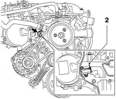
7. Disconnect the oil pressure sensor wiring connector, ECT and CMP sensors.
8. Remove the CMP sensor from the timing case.
9. Disconnect the hoses from the water pump.
10. Disconnect the stepper motor and throttle potentiometer connector.
11. Remove the throttle cable and holder.
12. Disconnect all hoses of the cooling system, vacuum hose and PCV hose from the throttle body.
13. Disconnect the instrument panel multi-pin connector (lower).
Disconnect the battery at least 20 seconds before.
14. Remove the evaporator control valve with holder.
15. Pinch fuel hoses clips and disconnect them from the holder.
16. Disconnect the brake booster vacuum hose near the exhaust manifold.
17. Remove the back holder of electroconducting from the inlet pipeline.
18. Turn out the top bolt of a support of the inlet pipeline, weaken the bottom bolt of a support.
19. Remove the bottom holder of electroconducting from the inlet pipeline.
20. Disconnect the contact bus of the injectors, pull up and take it to the side.
21. Give bolts of fastening of a pulley of the water pump.
22. Remove the accessory drive belt.
23. Remove the water pump pulley.
24. Remove the bottom drain plug from the water pump and collect the escaping fluid in a suitable container.
25. Disconnect the hoses from the expansion tank of the cooling system.
26. Remove the reservoir from the bulkhead of the engine compartment.
27. Remove the cylinder head cover.
28. Turn out 3 bolts of fastening and remove a cover of the case of the thermostat.
29. Set the piston of the first cylinder to the TDC position (see Section In-Vehicle DOHC Gasoline Engine Repair Procedures).
The position of the crankshaft corresponding to the position close to TDC is necessary so that the crankshaft locking pin can be easily inserted.
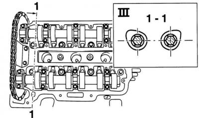
30. In the indicated position, the camshaft cams that control the gas distribution in the first cylinder (section 1-1) look outward from the same angle.
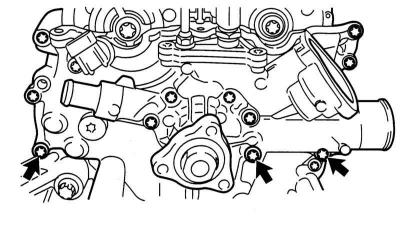
The orientation of the cams when installing the piston of the first cylinder in the TDC position
31. Remove the cork (1) under the crankshaft pin.
Cork (1) under the crankshaft pin
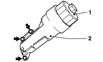
32. Insert the crankshaft lock pin (1) (KM-952) into the bore of the cylinder block plate and rotate the crankshaft at the center bolt evenly and slowly in the direction of engine rotation so that the lock pin engages in the groove of the crankshaft. In this case, the crankshaft is in the TDC position of the piston of the first cylinder.
Devices for fixing the crankshaft (1) and distribution (2) shafts
33. Fix the camshaft with a special tool KM-953 (2) in the TDC position (refer to illustration).
If the instrument (KM-954) there is no CMP sensor washer to fix, mark with a scriber the position of the intake camshaft gear in relation to the timing case and the position of the phase sensor washer in relation to the camshaft gear.
34. Unscrew the guide tube of the dipstick for measuring the oil level and pull it up.
35. Disconnect the lambda probe connector.
36. At the corresponding complete set disconnect a socket of the K/V compressor.
37. Remove the mounting bolts and disconnect the catalytic converter from the exhaust manifold. Remove the seal.
38. With the appropriate configuration, unscrew the mounting bolts and disconnect the K / V compressor from the timing case.
Do not open the A/C cooling circuit. The refrigerant contained in it can cause frostbite.
39. Turn out bolts of fastening and remove lock levels of the engine over an exhaust manifold.
40. Turn out bolts of fastening and remove the top thermofilter of a final collector.
41. Remove the oil filter cap (1).
Oil filter cap and housing
Cover the catalytic converter so that oil does not drip onto it when removing the oil filter housing.
42. Remove the oil filter housing (2) from cylinder block (arrow) (refer to illustration). Place more rags to collect the leaking oil.
43. Disconnect the EGR valve connector (1) and temperature sensor (3).
EGR sensor connector (1), temperature sensor (3) and cooling circuit fitting (2)
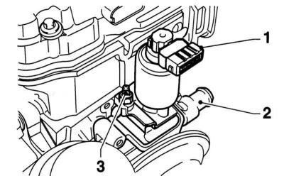
44. Disconnect the coolant hose (2) from the EGR valve body (refer to illustration).
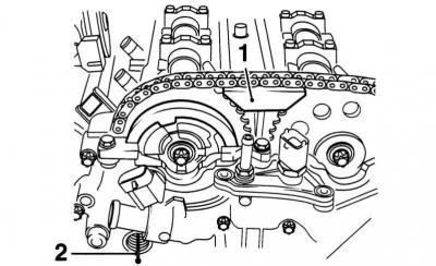
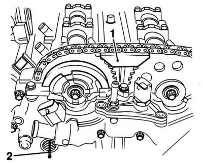
45. Remove the plug from the chain tensioner hole (arrow).
Timing chain tensioner plug and fixing rod (2)
46. Press the chain tensioner back with a screwdriver and secure with a suitable rod (2) (refer to illustration). To do this, you can use the device KM-955.
47. Remove spacer (1).
Spacer (1) and chain tensioner pin (2)
48. Loosen the camshaft sprockets. To do this, hold the camshafts with a wrench by the hexagon in the area of \u200b\u200bthe timing control cams of the first cylinder.
The camshaft locking tool is not designed to hold the camshafts.
49. Remove the sprockets with the CMP sensor washer from the camshafts and discard the chain from them.
50. Hang the chain on the timing case so that it cannot fall into the case.
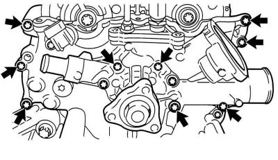
51. Turn out bolts of fastening of the case of a drive of GRM.
Bolts of fastening of the case of the drive GRM
52. Remove the tool for fixing the camshafts.
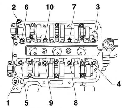
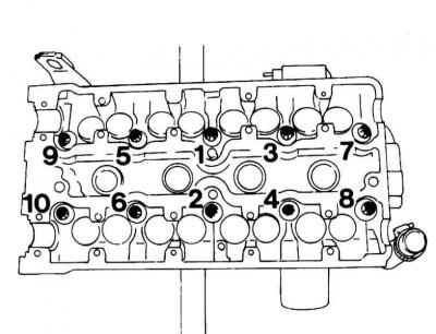
53. Give bolts of fastening of a head of cylinders in sequence from 1 to 10 at first on a quarter of a turn, then on a half-turn and then turn out them completely.
Order of giving of bolts of fastening of a head of cylinders
54. On the engine 1.2L DOHC Give bolts of fastening of a head of cylinders in sequence from 1 to 12 as it is described above. When doing this, start with the top left bolt (bolt (2)) (in the illustration) and then release the rest of the bolts in a counterclockwise spiral.
55. Press the cylinder head towards the gearbox and remove the head from the cylinder block.
The locking pin for the chain tensioner must be guided through the hole in the timing case.
56. Lay the cylinder head on two wooden supports so as not to damage the valves.
57. Remove the cylinder head gasket (1).
Cylinder head gasket
58. Bend the distributor housing gasket at break points (arrows) and cut the working edges of the gasket in the center (refer to illustration). Be careful not to leave any of the sealing lips of the cylinder head gasket.
59. Remove all gaskets and gasket residue.
Preparing for installation
See Section Removal and installation of a head of cylinders.
Installation
Engines 1.4 and 1.6 l
1. Clean the mating surface of the cylinder block from sealant residues with a scraper. Make sure that dirt does not get into the holes of the block. Close the holes with a clean cloth.
The threaded holes of the cylinder head bolts must be free of oil and coolant. Blow out the holes with compressed air or remove the liquid with a screwdriver with a rag wrapped around it. Otherwise, when screwing in new bolts, cracks may form in the block, and the tightening torque values \u200b\u200bwill be distorted.
2. Check the curvature of the mating surface of the cylinder block (see part General and overhaul of the engine this chapter).
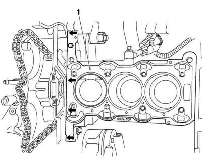
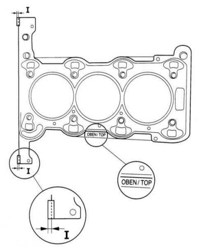
3. Lay a new gasket without sealant on the degreased mating surface of the cylinder block. The gasket must be laid in such a way that none of the openings are covered. Inscription «OBEN/TOP» on the gasket must face up and towards the engine timing belt.
4. Clean the mating surface of the cylinder head.
5. Check the curvature of the mating surface of the cylinder head (see part General and overhaul of the engine this chapter).
6. Install the cylinder head and evenly tighten the new mounting bolts to fit in the order indicated in the accompanying illustration.
The procedure for tightening the cylinder head bolts
Be sure to use new mounting bolts.
7. Bolts should be tightened in five steps: first tighten them firmly 25 Nm, then - turn them three times at an angle 90 deg., and finally, tighten the bolts at an angle 45 deg.
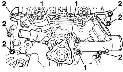
8. Tighten bolts of fastening of a back top cover of a gear belt with effort 6 Nm.
9. Establish cogwheels of camshafts, keeping a shaft from turning for inflow a wrench. Tighten the new camshaft mounting bolt to 65 Nm.
Be sure to use new mounting bolts.
10. Establish a cover of a head of cylinders and tighten bolts of its fastening crosswise with effort 8 Nm.
11. Install the starter (see chapter Engine Electrical Systems).
12. Fix a reception pipe of system of release on a collector with force 25 Nm and on the connecting flange of the catalytic converter with a force 18 Nm.
13. Install the toothed belt (see Section Removing and installing timing belt (engines 1.4 and 1.6 l)).
14. Establish a forward cover of a gear belt.
15. Tighten with force 4 Nm fasteners for the cover of BB wires.
16. Further installation is carried out in the reverse order to the dismantling of the components.
17. Fill the cooling system (see Section general information), and check and, if necessary, correct the oil level in the engine. If the cylinder head was removed due to damage to the gasket, change the oil and filter, as There may be coolant in the oil.
Engines 1.0 and 1.2 l
1. Clean the mating surfaces of the cylinder block and timing case from sealant residues. Make sure that dirt does not get into the holes of the cylinder block.
The threaded holes of the cylinder head bolts must be free of oil and coolant. Blow out the holes with compressed air or remove the liquid with a screwdriver with a rag wrapped around it. Otherwise, when screwing in new bolts, cracks may form in the block, and the tightening torque values \u200b\u200bwill be distorted.
2. Clean the mating surface of the cylinder head.
3. Check cylinder head distortion (see part General and overhaul of the engine this chapter).
Grinding of the cylinder head is not permitted.
4. Cut off the projections of the new cylinder head gaskets (size I) on the side of the timing case.
Cut points and mark of the top of the cylinder head gasket
5. Install the camshaft sprockets with the chain put on them in the timing case.
6. Apply rollers (1) 2 mm silicone sealant on the corners of the timing case/cylinder block.
Application of sealant (1) at the junction of the timing cover with the cylinder head and the bolts of the timing drive housing
Use only OPEL sealant, ET No. 90 543 772. After applying the sealant, the cylinder head and timing case must be installed and tightened with bolts for 10 minutes.
7. Install a new cylinder head gasket so that any of the holes are not blocked. Inscription «OBEN/TOP» on the gasket should face up. Press the gasket against the silicone sealant.
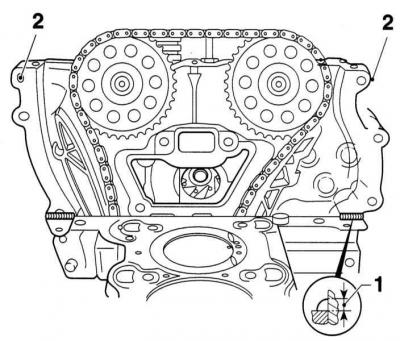
8. Insert both top bolts (2) fastening of the timing drive housing on the left and right (refer to illustration).
9. Hang the sealing gasket at the top with holes on the left and right on the bolts, and press it down, in the area of the applied silicone sealant.
10. Apply two other rollers to the corners of the timing case and cylinder head gasket.
11. Insert the camshaft retainers. If the retainer does not fit, slowly turn the shafts by the hex.
12. Install the cylinder head on the block. At the same time, make sure that the locking pin for the chain tensioner passes through the hole in the timing case and the chain tensioner past the tensioning plate.
13. Press the cylinder head against the timing case.
14. Screw in the 3 lower bolts of the cylinder head to the timing case and tighten them with force 8 Nm.
Lower cylinder head bolts to timing case
15. Once again, with light blows of a plastic hammer, correct the position of the cylinder head in the direction of the timing case.
16. Remove the camshaft retainer.
17. Insert new bolts of fastening of a head of cylinders and tighten them before adjoining to a head of cylinders. Then tighten the cylinder head bolts in four steps in sequence from 1 to 10: first - with a force 25 Nm, and then turn them three times at an angle 60 deg.
The procedure for tightening the cylinder head bolts
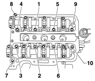
18. On the engine DOHC 1.2L tighten the cylinder head bolts in sequence 1 to 12 also in four steps. While tightening, start with the central bolt in the top row of bolts and continue in a clockwise direction. So the bolt is on the top left (bolt (8) (in the illustration) dragged on last.
19. Again give 3 lower bolts of fastening of a head of cylinders to the case of a drive of GRM.
20. Tighten the mounting bolts first (1) water pump to the cylinder head with force 8 Nm, and then bolts (2) timing case to the cylinder head with a force 8 Nm.
Water pump mounting bolts (1) and timing case (2) to the cylinder head
21. Install the camshaft retainer. If the retainer does not fit, slowly turn the camshafts by the hexagon.
22. Install sprockets with chain on camshafts.
If a CMP sensor rotor jig is not available, install the sprocket so that the mark made during removal lines up with the timing case.
23. Press the CMP sensor rotor against the intake camshaft sprocket and secure the sprocket lightly with a new bolt. Tighten the bolt so that the CMP sensor rotor can still rotate.
24. Also lightly tighten the exhaust camshaft sprocket bolt.
25. Insert the top spacer and secure it firmly 8 Nm.
26. Remove the chain tensioner retainer.
27. Install the jig (1) CMP sensor rotor (KM-954) and attach it to the timing case. If necessary, turn the rotor of the CMP sensor so that the jig can be installed.
CMP sensor rotor jig
If there is no CMP sensor rotor guide, turn the rotor so that the mark made before removal matches the mark on the camshaft sprocket. At the same time, the mark on the camshaft sprocket must align with the timing case. In this position, tighten the camshaft sprocket bolt. When doing this, make sure that the CMP sensor rotor does not rotate relative to the camshaft sprocket.
28. Tighten the camshaft sprocket bolts with force 50 Nm and tighten the bolts one more angle 60 deg. At the same time, hold the camshaft from turning with a wrench by the hexagon.
Locking mandrels must not be used as a holding tool.
29. Remove all locking mandrels and check the valve timing. To do this, turn the crankshaft 2 revolutions in the direction of engine rotation and stop at TDC on the first cylinder. If, in this position, the locking mandrels are inserted simultaneously and without problems, the distribution phases have been adjusted correctly.
30. Tighten the plug of the hole for the chain tensioner with a force 20 Nm.
31. Install the CMP sensor with a new O-ring on the timing case.
32. Tighten the plug of the hole for the stopper of the crankshaft with a force 60 Nm.
33. Put the cooling system hose on the AGR body and secure it with a clamp.
34. Connect the connectors of the AGR valve and the temperature sensor.
35. Install the oil filter housing with a new sealing ring on the cylinder block and tighten its fasteners with force 20 Nm. Attach the cover to the housing with a new O-ring.
36. Install the upper exhaust manifold heat shield and tighten its fasteners with force 8 Nm.
37. Install the engine stop bars and tighten their fasteners with force 20 Nm.
38. With the appropriate configuration, install the K / V compressor on the timing case and cylinder block and tighten its fasteners with force 20 Nm.
39. Fasten the catalytic converter with a new seal to the exhaust manifold by hand without tightening the mounting bolts.
40. Screw by hand, without tightening, bolts of fastening of the holder of the catalytic converter.
41. Install the catalytic converter and tighten its fasteners with force 35 Nm, and the fastener of the holder - with a force 15 Nm.
42. At the appropriate complete set connect a socket of the K/V compressor on the holder.
43. Install the dipstick guide tube with a new gasket and tighten its fasteners to the exhaust manifold with force 8 Nm.
44. Further installation is carried out in the reverse order of dismantling the components. Tighten fasteners to the required torque.
45. At the end of the installation, fill the cooling system, and also check and, if necessary, correct the oil level in the engine. If the engine was removed due to damage to the cylinder head gasket, change the oil and oil filter, as There may be coolant in the engine oil.
Visitor comments