
General information
Anti-lock brake system (ABS) included in the additional package of the considered models.
When the vehicle is equipped with a conventional brake system, depressing the foot brake pedal suddenly causes the wheels to lock. In this case, the grip of the tread with the road surface is disturbed, and the car can go skidding, losing controllability. Anti-lock brake system (ABS) prevents premature blocking of the wheels by continuously controlling the speed of their rotation during braking by modulating the pressure of the hydraulic fluid in each of the brake mechanisms.
ABS consists of two main subsystems: electrical and hydraulic. The electrical part of the system includes four wheel speed sensors, a control processor and a set of connecting wiring. The hydraulic part includes a pressure modulator, disc brake calipers and hydraulic lines connecting the components.
ABS System Components
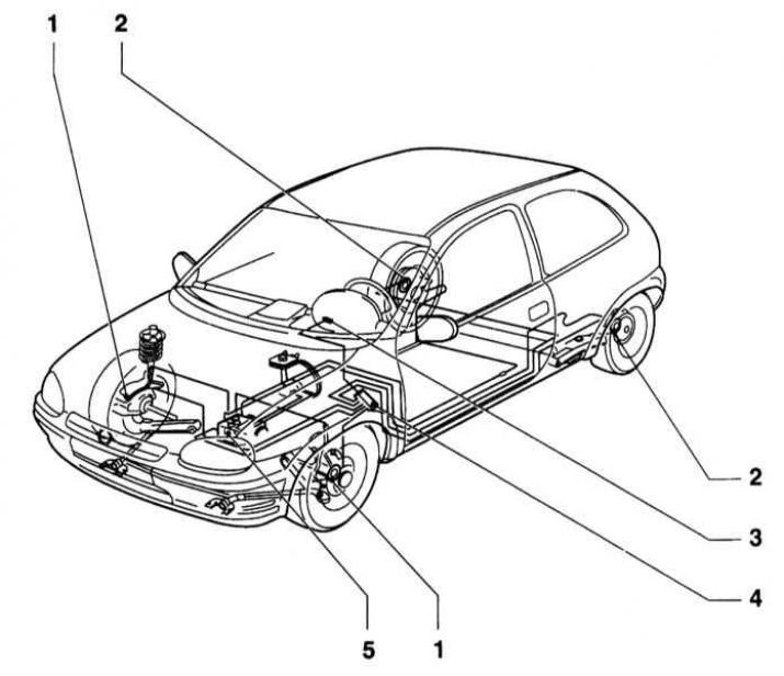
1 - Front wheel sensors
2 - Rear wheel sensors
3 - Control lamp
4 - ABS control unit
5 - Hydromodulator
The principle of operation of the system is quite simple. Each of the wheels is equipped with an individual speed sensor. The sensor consists of a rotor (rings with teeth evenly spaced around its perimeter) and a sensitive element in the form of a magnetized coil. The sensitive element of the sensor captures the moments of the passage of the teeth of the rotor and converts the information received into electrical signals that are continuously transmitted to the ABS control processor. Based on the results of processing the incoming signals, the processor receives information about the relative speed of rotation of each of the wheels. As long as all four wheels rotate at the same speed, ABS is in a passive state. As soon as any of the wheels starts to block, the processor detects a change in the input signal and generates a command to operate the modulator, which instantly relieves the pressure of the hydraulic fluid in the brake mechanism of the corresponding wheel. As soon as the normal rotation of the wheel is restored, the processor suspends the operation of the modulator.
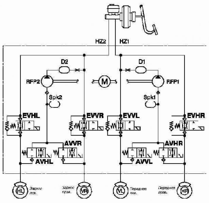
Principle of operation of ABS brake circuit in parallel configuration
Normally open in the absence of signs of blocking the wheels inlet e / m valve (EV) provides full hydraulic pressure to the wheel brakes. Mode «holding pressure» turns on when power is applied to the valve. The required pressure reduction is ensured by actuation of the outlet (AV) and inlet (EV) valves, as well as a return pump (RFP)
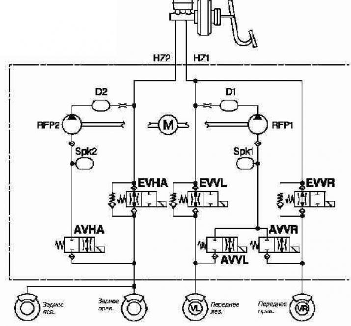
The principle of operation of the diagonal configuration ABS brake circuit
Brake fluid enters the accumulator and is pumped by the return pump (RFP) through damper chamber (D) back to the GTZ, which allows you to smooth out pressure peaks, thereby reducing background noise. Control valves connected in parallel with the EV valve provide the ability to quickly reduce pressure when the brake pedal is released
V - Front brakes
R - Right wheel brake
H - Rear brake mechanisms
L - Left wheel brake
EV - intake valve
AV - Exhaust valve
In order to prevent false signals from affecting the functioning of the ABS, a special safety circuit is built into its control system. If an inadequate signal is received by the control unit, as well as if the supply voltage level drops excessively, the system automatically turns off, and the ABS warning lamp lights up on the instrument panel (see chapter Controls and methods of operation at the beginning of the guide). The braking system continues to function normally.
In reality, the functioning of the ABS system is much more complicated than it might seem, so the compilers of this manual do not recommend car owners to attempt to repair the system on their own. In the event of a malfunction, it would be most reasonable to contact the car service specialists, where the appropriate diagnostics will be carried out using a scanner reader connected to the DLC connector (see chapter Power supply systems, release and reduction of toxicity of exhaust gases).
Reading ABS Fault Codes
When starting the engine, the ABS warning lamp on the instrument panel of the vehicle should turn on briefly and go out again almost immediately. If, due to any violation, the lamp remains on after the engine is started, the ABS processor writes the corresponding digital code to the memory of the self-diagnosis unit. Codes are read using a special scanner connected to a 16-pin diagnostic connector located under the front sill of the driver's door of the car. In the absence of a scanner at hand, the car should be driven away to read the memory and perform the necessary restoration repairs to a service station. The identification card of the ABS diagnostic codes is given in the Specifications of the Chapter Brake system.
Clearing ABS memory
After fixing the identified problems in the system, the processor memory should be cleared. To clear the memory, you will again need a scanner, in the absence of which the car will have to be driven to a service station. For more information on the scanner reader, see Chapter Engine Electrical Systems.
Visitor comments