
The special ceramics of the probe are exposed to the exhaust gases on the outside and come into contact with the atmospheric air on the inside.
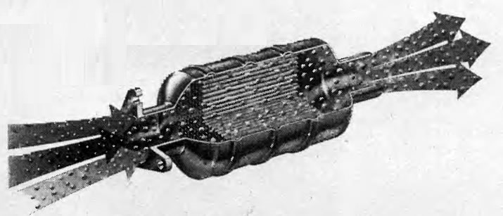
Here is a schematic representation of the operation of a catalytic converter. NOx emissions from the engine (nitrogen oxides), CO (carbon monoxide) and NA (hydrocarbons). After the reaction, N leaves the catalytic converter2 (nitrogen), CO2 (carbon dioxide) and H2O (water).
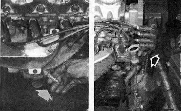
Left: In the eight-valve Vectra engine with a displacement of 1.6 liters, a lambda probe (arrow) located directly in the exhaust manifold. The removal of the lambda probe is described in the injection chapter.
On right: The connector for the lambda probe wires is located on the right side of the engine under the DIS ignition module.
Due to the different oxygen content in the exhaust gases and in the atmospheric air, the probe creates a voltage that increases sharply at a certain residual oxygen content in the exhaust gases. This voltage jump occurs exactly at the ratio of fuel and air, when λ=1. With a lack of oxygen (λ less than 1), i.e. with a rich air-fuel mixture, the voltage is 0.9-1.1 V. With a lean air-fuel mixture (λ is greater than 1) 0.1 V is reached.
The lambda signals are sent to the injection system control unit. From there, the air-fuel mixture is influenced so as to keep the fuel/air ratio as close as possible to λ=1.
The lambda probe reacts to fluctuations in the amount of oxygen depending on its operating temperature at different speeds: at 300°C it reacts in about 1 second, at 600°C in less than 50 ms. О Due to the built-in heating in 1.8-2.0 l engines, the most favorable operating temperature of approximately 600°C is reached faster.
Visitor comments