
Cylinder head and camshaft
To improve thermal conductivity and save weight, the cylinder head is made of light metal. The valve seats are inserted into the heated cylinder head and due to this, after it cools down, they are firmly seized. The spark plugs are screwed directly into the cut threads in the cylinder head. This thread can be damaged if the spark plug is screwed in too tightly or inserted obliquely and overtightened.
At the top of the cylinder head is the camshaft. He has five pillars. It acts with its egg-shaped cams so that they open and close the valves at certain positions of the pistons. The shape and location of the cams determine the valve timing. The camshaft is driven by the crankshaft via a toothed belt.
Valve distribution
Control «hanging» valves are carried out by a short transmission path: the cams press on the pendulum lever - a kind of intermediate support - and through this on the valves, opposing the force of the valve spring. Thus, the gap between the valve disc and the valve seat opens, the valve opens. As the cam moves further, the valve spring pushes the valve back to the closed position.
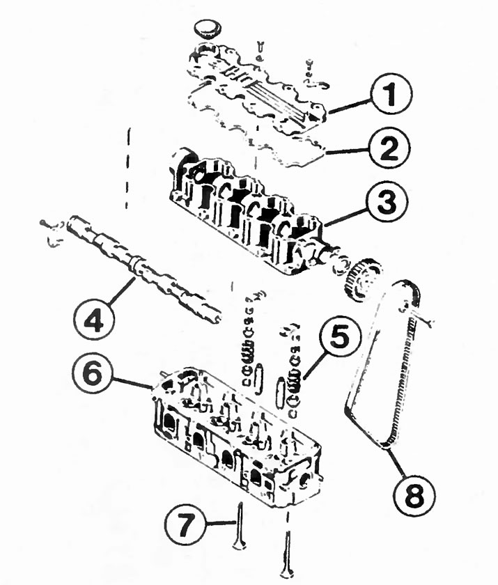
This shows the design of the cylinder head of an 8-valve engine with a displacement of 1.6 liters. The numbers indicate:
1 - cylinder head cover;
2 - gasket;
3 - camshaft housing;
4 - camshaft;
5 - valve spring;
6 - cylinder head;
7 - valve;
8 - toothed belt.
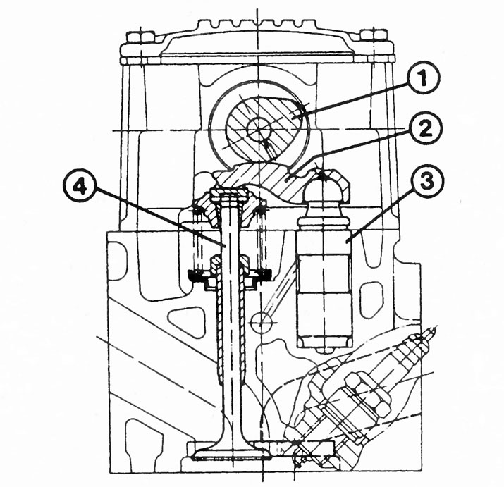
The figure in the section of the cylinder head of an 8-valve engine shows the following structural units:
1 - camshaft;
2 - pendulum lever;
3 - hydraulic valve clearance adjuster (hydropusher);
4 - valve.
The intake and exhaust valves are located in the cylinder head offset from each other, and hydraulic pushers are inserted against each (hydraulic valve clearance adjusters). These hydraulic tappets compensate for changes in valve length that occur as a result of temperature effects and wear.
The impact of the hydraulic pusher is transmitted to the valve by means of a pendulum lever. This ensures that the entire valve train operates without play, and the otherwise necessary additional adjustment of the valve play becomes redundant. The air-fuel mixture inlet is located at the rear in the direction of travel, the outlet channels are located on the front side. This principle of the transverse movement of the mixture flow corresponds to the location of the intake and exhaust valves.
The valves run in alloy guides made of gray cast iron, which are pressed into the cylinder head. A valve stem gasket is fitted over each guide. All exhaust valves are «Roto Caps» (valve turning mechanisms). They turn the valves a few degrees on each stroke, thereby delaying «hammering» seat surfaces and therefore loss of compression.
Valve timing
It is known that in the Vectra we have a four-stroke engine, which sucks in a mixture of gasoline and air on the 1st stroke, compresses it on the 2nd stroke, ignites it on the 3rd stroke and pushes the burnt gases out on the 4th stroke. A valve-controlled internal combustion engine has very little time to suck in the combustible mixture and exhaust the exhaust gas. The camshaft cannot open the valves instantly, and the valve springs cannot close them as quickly. Therefore, the cams are designed in such a way that the intake valve opens already at the end of the exhaust stroke and closes only after the piston, compacting the mixture, rushes forward again after the end of the suction stroke. The exhaust valve opens already before the end of the working cycle and closes only when the piston has already sucked in the combustible mixture. Therefore, for a fraction of a second, both valves remain open at the same time when the piston is at top dead center (TDC) from pushing back to suction. This period of time is called «valve overlap».
Hydraulic pushers
All Vectra models are equipped with hydraulic valve lash adjusters, the so-called hydraulic tappets. Such a device makes it possible to refuse to control the valve clearance: the valve mechanism works without clearance, but, nevertheless, ensures a tight fit of the closed valves to the seats and perfect sealing.
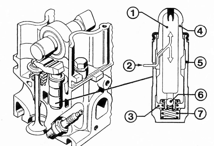
Shown here is the design of a hydraulic valve clearance adjuster (hydraulic pusher) in an 8 valve engine:
1 - oil tank;
2 - oil supply;
3 - injection chamber;
4 - piston (mobile);
5 - discharge cylinder (fixed);
6 - check valve;
7 - expansion spring.
Tip: If the machine has not been used for a long time, an engine equipped with hydraulic tappets may make a knocking noise similar to damaged bearings shortly after the first start. This effect occurs if all the oil has flowed out of the hydraulic tappets and a gap has again appeared in the valve mechanism. There is no reason for concern: the knock soon disappears, and the valve mechanism again begins to work silently.
If one of the hydraulic pushers knocks for a long time and even when the engine is warm, then it must be replaced.
Function of hydraulic pushers
When the valve is closed, oil from the engine lubrication circuit flows through the hole into the hydraulic tappet oil reservoir. After passing through the non-return valve, the lubricant flows into the pressure chamber, which is currently not under pressure, and completely fills it.
In parallel with this process, the expansion spring presses the piston tightly against the pendulum arm, which, in turn, fits without play on the camshaft cam, as well as on the end of the valve.
When the camshaft turns and presses the eccentric cam against the hydraulic pusher piston, the pressure in the injection chamber rises. The non-return valve closes the intake port and oil cannot escape. Because oil cannot compress, this creates a rigid connection between the hydraulic pusher, pendulum lever, camshaft and the end of the valve stem. The valve can be pushed down by the force of the cam. After closing the valve, there is a slight gap in the valve due to leakage, which is immediately compensated by the expansion spring - it presses the valve upwards. Oil flows again into the increased volume of the pressure chamber with the check valve open. This makes the hydraulic tappet ready for the next actuation of the valve.
Toothed belt
The silent drive element of the overhead camshaft is a toothed belt driven by the crankshaft. Toothed rubber belt reinforced with steel wire is not subject to wear; in addition, the rubber compound of the toothed belt provides dry lubrication of the belt pulleys.
In addition, the toothed belt drives the water pump. Next to the water pump is an automatic tensioner that maintains a constant tension on the toothed belt.
Cylinder head gasket
The gasket between the engine block and the cylinder head must separate the combustion chambers and coolant passages from each other, while it must also not allow lubricating oil to pass through. It must withstand high fluctuations in temperature and pressure.
Vectra engines are about «laying with a small draft». Therefore, when installing the cylinder head, the bolts must be tightened according to a special sequence of work steps.
Visitor comments