


Contents: Relay function ⬇ Troubleshooting Relays ⬇ Temporary roadside assistance for a…⬇ Multitimer ⬇
The on-board electrical equipment includes a number of relays, which are all located together in the relay box in the engine compartment behind the fuse box or in the fuse box. Furthermore, the Vectra has several switching devices and control units, which are installed in the car in different places on separate connecting nodes.
A simple switching relay is used for powerful consumers of electricity. If the current is supplied by bypass paths through the corresponding switches, there are voltage losses. In addition, the contacts of the switches are subject to a strong load due to the high current. With a relay connection scheme, the switch is used only for a small switching current, and it is not the consumer that is connected directly, but its relay.
Certain relays can perform additional functions. For example, the flasher relay switches on intermittent light signals, the interval relay in the windshield wiper/washer system controls the intermittent operation mode and the operation of the windshield wipers "dry" after washing the windshields. There are no such relays in our Vectra. In this case, all these functions are performed by the multi-timer.
Switching devices and control units have more or less extensive electronic circuits to perform certain functions, sometimes a relay is also built in. Examples include the ignition/injection control unit or the airbag control unit.
Relay function
When the corresponding consumer is switched on, due to the "switching current" supplied to terminal 86, the switching electrical circuit in the relay is closed at terminal 85.
As a result, the electromagnetic coil attracts a powerful contact against the pressure of the spring, and thus closes the electrical circuit for the "working current".
The operating current, in order to avoid a voltage drop, is supplied via a short path directly to terminal 30 of the relay and from there further - with the switch contacts closed - through terminal 87 to the current consumer.
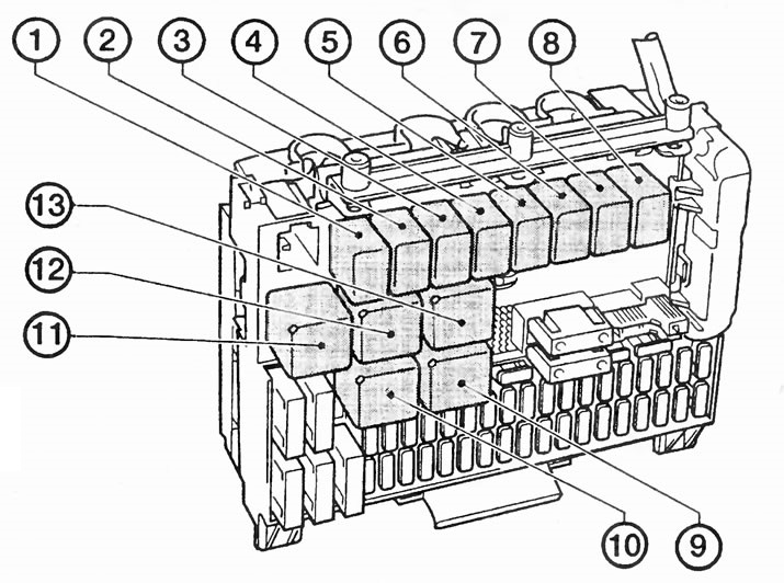
There are numerous relays located in the fuse box:
1 - Fanfare/sound horn (K63);
2 - high beam headlights (K73);
3 - rear window wiper (K120);
4 - heated external viewing mirror (K121);
5 - fog lights (K5);
6 - fog lights (K89);
7 - right turn signal lamp (K123);
8 - left turn signal lamp (K122);
9 - heated rear window (K1);
10 - air conditioning system supercharger (K7);
11- climate control (KB);
12 - air conditioning system supercharger, 1st stage (K64);
13 - windshield wipers (K124).
Troubleshooting Relays
There should always be voltage at terminal 30, unless it is a relay whose consumer depends on another. Example: the fog light relay receives current only if the light is on.
To check, pull the corresponding relay out a little and tap the test lamp needle on terminal 30.
Disconnect the relay, connect terminal 86 to the battery positive and terminal 85 to ground. You should clearly hear the electromagnetic coil pulling the relay contact, otherwise the relay is faulty.
Temporary roadside assistance for a faulty relay
Material taken from an internet portal: www.OPELBOOK.ru
Remove the relay from the socket.
Short-circuit terminals 30 and 87 in the relay socket with a paper clip or a piece of wire. This will ensure that the corresponding consumer receives current continuously.
To turn it off, remove the jumper, since this switch is blocked in this case.
Multitimer
The fuse box has a removable multi-timer integrated into it – an electronic jack of all trades that can simultaneously control various time and switching functions. The small electronic component, among other things, switches off the rear window heating and the outside view mirror after at least 15 minutes of operation, as well as the lights, fog lights and fog lamps after the ignition is switched off.
Visitor comments