OpelBook.ru
Cars AvtoVAZ Cars Mitsubishi Cars BMW Cars Mercedes Cars Nissan Cars Toyota Cars Chevrolet
English Русский
Български
Беларускі
Український
Српски
Hrvatski
Română
Polski
Slovenský
Magyar
 |  Sitemap  |  Contacts  |    


Main Astra Corsa Insignia Kadett Omega Vectra Zafira Others Articles
Omega A (1986-1993) Omega B (1993-1999) Omega B2 (1999-2003)
  • Main
  • Omega
  • Omega B
  • Power unit
  • Petrol engines 2.5 and 3.0 l
  • Gas distribution belt

Gas distribution belt (Opel Omega B)

            0

Contents: Removal ⬇ Installation ⬇
Timing Belt Adjustment Tools
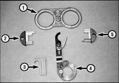
1. KM-800-20

1. KM-800-20

2. KM-800-1

3. KM-800-30

4. KM-800-10

5. KM-800-2


To adjust the timing belt, you will need the following special tools: camshaft sprocket locking tools (KM-800-1 and KM-800-2), a tool for locking the crankshaft sprocket (KM 800-10), a wedge for the timing belt (KM-800-30) and a tool for synchronizing the camshaft sprockets (KM-800-20).

Removal


1. Disconnect the negative battery cable and set piston N1 to TDC.

2. Remove the crankshaft pulley.

3. Check if the synchronization marks are aligned correctly.
3. Check if the synchronization marks are aligned correctly.


4. Install the KM-800-10 tool on the crankshaft sprocket and lock the shaft.
4. Install the KM-800-10 tool on the crankshaft sprocket and lock the shaft.


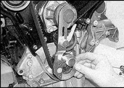
5. Lock the camshafts, tool KM-800-1 (marking 1 and 2, red handle) is designed for the shafts of the right cylinder head, and the KM-800-2 tool (marking 3 and 4, green handle) for left head shafts. Clamp the tool lever on the water pump flange.
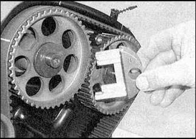

5. Lock the camshafts, tool KM-800-1 (marking 1 and 2, red handle) is designed for the shafts of…


5. Lock the camshafts, tool KM-800-1 (marking 1 and 2, red handle) is designed for the shafts of…


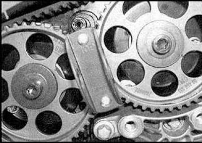
6. Install the camshaft sprocket locking tool (drawing on the left). The TOR marks should be facing upwards (drawing on the right).
6. Install the camshaft sprocket locking tool (drawing on the left). The TOR marks should be facing…


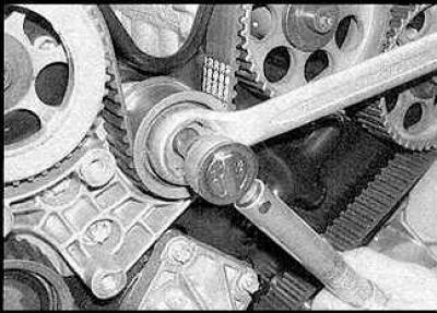
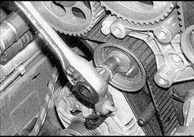
7. Loosen the timing belt tensioner pulley nut.
7. Loosen the timing belt tensioner pulley nut.


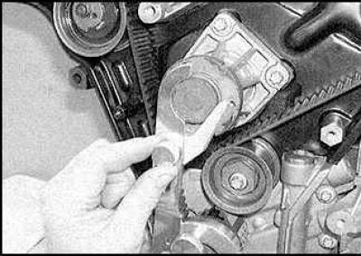
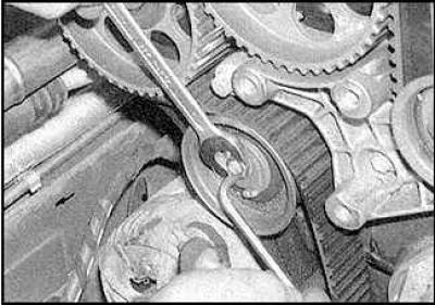
8. Turn the tensioner pulley clockwise until it stops and tighten the nut.
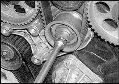


8. Turn the tensioner pulley clockwise until it stops and tighten the nut.
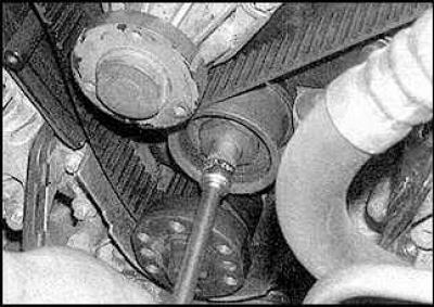

8. Turn the tensioner pulley clockwise until it stops and tighten the nut.


9. Loosen the top bolts (drawing on the left) and lower (drawing on the right) timing belt guide pulleys.

10. Remove the timing belt. If you did not use special tools, turn the crankshaft approximately 60° back before removing the belt. This reduces the likelihood of the valves touching the pistons.

11. Carefully inspect the belt for wear and damage and replace it if necessary.

Installation


Adjusting the tensioner pulley
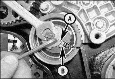
A. Tensioner pulley mark

A. Tensioner pulley mark

B. Stop mark


Warning! There are two types of belts and two types of tensioners that are installed on the engines described. The type of tensioner determines the type of belt. Modified tensioners are installed on engine models produced in 1997 and later and are marked E on the pulley. Regular tensioners are installed on engine models produced before 1997 and are marked D. If you have difficulty determining the type of tensioner, consult a specialist.


1. Clean the shaft sprockets and pulleys thoroughly.
1. Clean the shaft sprockets and pulleys thoroughly.

1. Clean the shaft sprockets and pulleys thoroughly.


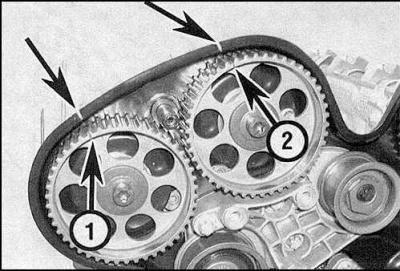
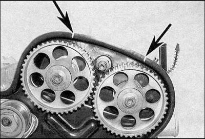
2. Align the timing marks of the camshaft sprockets of the right cylinder head (1 and 2) (drawing on the left) and left (drawing on the right) with the slots in the rear timing belt cover and re-align them if you have turned the crankshaft 60°.


2. Align the timing marks of the camshaft sprockets of the right cylinder head (1 and 2) (drawing…


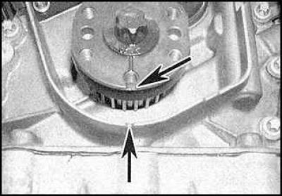
3. Align the crankshaft sprocket mark with the slot in the oil pump housing (indicated by arrows).
3. Align the crankshaft sprocket mark with the slot in the oil pump housing (indicated by arrows).


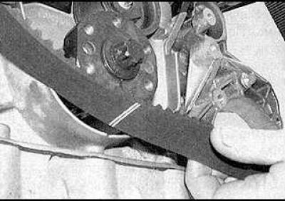
4. Place the belt on the sprockets. The arrows on the belt should point in the direction of belt rotation, and the double line on the belt should match the timing mark on the crankshaft sprocket.
4. Place the belt on the sprockets. The arrows on the belt should point in the direction of belt…


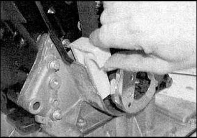
5. Lock the timing belt with a wedge.


5. Lock the timing belt with a wedge.


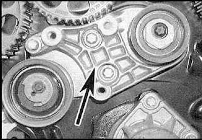
6. In engines equipped with a conventional tensioner, the belt must first be placed on the lower guide pulley and on the camshaft sprockets of the left cylinder head. Mark (indicated by the arrow) on the tensioner pulley bracket will help determine the tensioner type.
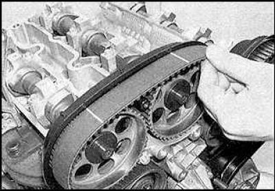
6. In engines equipped with a conventional tensioner, the belt must first be placed on the lower…


7. On engines equipped with a modified tensioner, the belt must first be placed on the tensioner pulley.
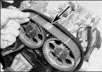
7. On engines equipped with a modified tensioner, the belt must first be placed on the tensioner…


8. Then the belt must be placed on the camshaft sprockets of the right cylinder head.
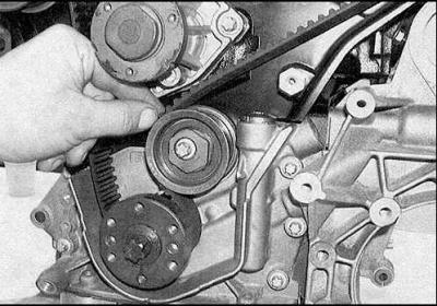


8. Then the belt must be placed on the camshaft sprockets of the right cylinder head.


9. Pass the belt over the lower idler pulley.
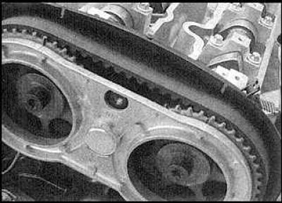
9. Pass the belt over the lower idler pulley.


10. Loosen the lower idler pulley bolt. Turn the pulley counterclockwise to tighten the left side of the belt. Check that the timing marks are still aligned.
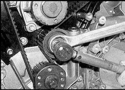
10. Loosen the lower idler pulley bolt. Turn the pulley counterclockwise to tighten the left side…


11. Tighten the pulley bolt.

11. Tighten the pulley bolt.


12. Loosen the upper idler pulley bolt. Turn the pulley counterclockwise to tighten the upper portion of the belt. Check that the timing marks are still aligned. Tighten the pulley bolt.
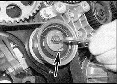


12. Loosen the upper idler pulley bolt. Turn the pulley counterclockwise to tighten the upper…


13. Loosen the tensioner pulley nut and turn the pulley lever counterclockwise so that the distance between the plate and the stop is 0.5–1.5 mm (indicated by the arrow). Tighten the nut.

14. Remove all locking tools and rotate the crankshaft two full revolutions.

15. Check that the sync marks are still aligned.

16. Loosen the tensioner nut and install the tensioner lever as shown in the figure (see figure Adjusting the tensioner pulley). The mark (A) should be 3-4 mm higher than the stop mark (B). Tighten the nut.

17. Rotate the crankshaft two full revolutions. Check that the timing marks are still aligned. Adjust if necessary.


This article is available at russian, bulgarian, belarusian, ukrainian, serbian, croatian, romanian, polish, slovak, hungarian
Checking the article: Fedorova Varvara

Share information:

Previous articles
Opel Omega B: Petrol engines 2.5 and 3.0 l
Next articles

Timing Belt Covers
Crankshaft pulley
Camshaft covers
Top dead center (TDC) of piston No. 1
Compression check
Technical specifications
Belt tensioner, sprockets and idler pulleys
Camshaft Seals — Replacement
Camshafts and tappets
Cylinder head
Oil pan
Oil pump


See similar ones from other Opel car manuals:
▶ Checking the timing belt of the gas distribution mechanism Opel Insignia A (2008-2017)
▶ Timing belt for gas distribution mechanism drive Opel Frontera B (1998-2004)
▶ Timing Belt Covers — Removal and Installation Opel Astra F (1991-1998, petrol)
▶ Checking the condition and replacing the auxiliary drive… Opel Corsa B (1993-2000)
▶ The device of the gas distribution mechanism of 8-valve… Opel Kadett E (1984-1995)
Link to this page in different formats

Visitor comments


No comments yet


How much will 24 + 36 =


Omega B2 (1999-2003) 
  • General information
  • User manual
  • Maintenance
  • Troubleshooting
  • Power unit
  • Petrol 4-cylinder
  • Petrol 6-cylinder
  • Engine overhaul
  • Diesel engines 2.0 l
  • Diesel engines 2.5 l
  • Cooling and heating
  • Injection system (gasoline)
  • Fuel system (diesel)
  • Fuel system
  • Exhaust system
  • Ignition system
  • Transmission
  • Clutch
  • Mechanical gearbox
  • Automatic gearbox
  • Main gear and shafts
  • Chassis
  • Brake system
  • Car suspension
  • Steering
  • Body
  • Body elements
  • Electrical equipment
  • Equipment and devices
  • Electrical circuits
Omega B (1993-1999) 
  • General information
  • User manual
  • Tips for the car owner
  • Maintenance (gasoline)
  • Maintenance (diesel)
  • Power unit
  • Petrol engine SOHC 2.0 l
  • Petrol engine DOHC 2.0 l
  • Petrol engines 2.5 and 3.0 l
  • Repair of gasoline engines
  • Diesel engine 2.0 l
  • Diesel engine repair 2.0 l
  • Diesel engine 2.5 l
  • Cooling and heating
  • Power system (petrol)
  • Emission reduction
  • Fuel system (diesel 2.0 l)
  • Fuel system (diesel 2.5 l)
  • Launch system
  • Ignition system
  • Transmission
  • Clutch
  • Mechanical gearbox
  • Automatic gearbox
  • Drive shafts
  • Chassis
  • Brake system
  • Wheel suspension
  • Steering
  • Body
  • Exterior
  • Interior
  • Doors and windows
  • Electrical equipment
  • Equipment and devices
  • Wiring diagrams (early)
  • Wiring diagrams (late)
Omega A (1986-1993) 
  • General information
  • User manual
  • Maintenance
  • Changes and additions
  • Troubleshooting
  • Power unit
  • Gasoline engines
  • Diesel engines
  • Cooling system
  • Fuel system (gasoline)
  • Fuel system (diesel)
  • Ignition system
  • Transmission
  • Clutch
  • Mechanical gearbox
  • Automatic gearbox
  • Cardan shaft
  • Drive shafts
  • Chassis
  • Brake system
  • Car suspension
  • Steering
  • Body
  • Exterior
  • Interior
  • Electrical equipment
  • Power devices
  • Lighting and appliances
  • Electrical circuits
OpelBook.ru © 2017–2026 · Mobile version · · Sitemap: EN BG BY UA RS HR RO PL SK HU · Feedback · Site search
Astra F, petrol · Astra G, petrol · Astra G · Astra H · Astra J, petrol · Corsa B · Corsa C, petrol · Corsa C · Insignia A · Kadett D · Kadett E · Omega A · Omega B · Omega B2 · Vectra A, petrol · Vectra A · Vectra B, petrol · Vectra B · Vectra C · Zafira A, petrol · Frontera A, petrol · Frontera B · Ascona C · Vivaro A ·
We want your visit to be comfortable 🤝! We use cookies 🍪 to make that happen.