


1. Remove the gearbox from the vehicle (see Removal and installation the gearbox). Clean it from dirt and wash the outside.
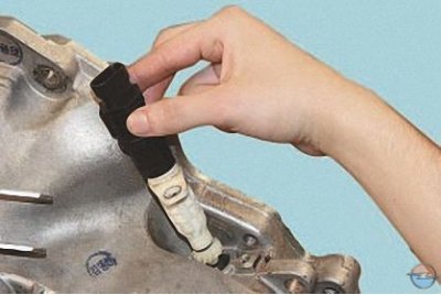
2. Remove the speedometer drive together with the vehicle speed sensor, if present (see Checking and replacing engine management system sensors).
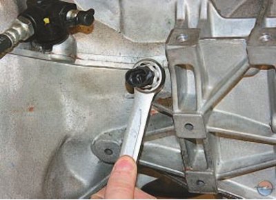
3. Loosen the reverse light switch…
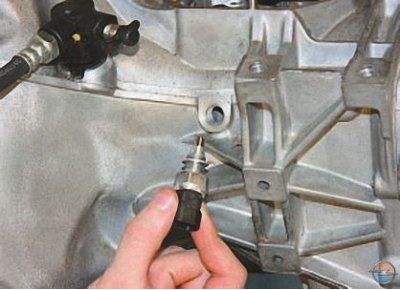
4. …and remove the switch.
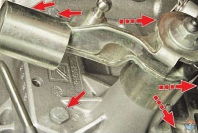
5. After unscrewing the bolts securing the gearshift mechanism housing, remove the mechanism…
Note: The three bolts that secure the gearshift housing are not visible in the photo.
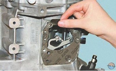
6. …and the gasket installed underneath it.
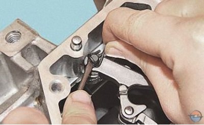
7. Using a screwdriver, pry up the spring retainer of the 5th gear engagement fork…
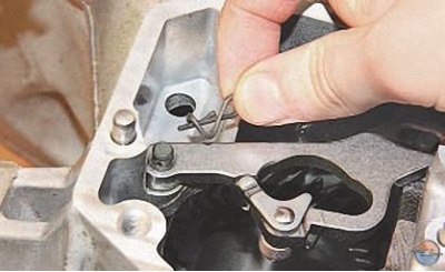
8. …remove the retainer…
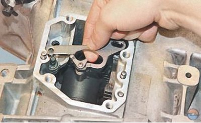
9. …and remove the leash.
10. Remove the clutch release drive slave cylinder assembly with the clutch release bearing (see Replacing the clutch release drive slave cylinder with release bearing) and a rubber sealing ring installed under the cylinder.
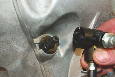
11. Remove the clutch release hydraulic drive adapter (see Replacing the clutch release hydraulic line).
12. Remove the intermediate pipe of the clutch release hydraulic drive (see Replacing the clutch release hydraulic line).
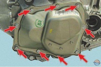
13. Remove the nine bolts securing the rear gearbox cover.
14. Using a screwdriver, pry the edge of the cover in the area of the lug specially designed for this purpose, separate the cover from the gasket and remove the cover.
15. Remove the cover gasket.
Note: Replace the transmission rear cover gasket with a new one each time the joint is disassembled, as a used compressed gasket may not provide a tight seal when reassembled.
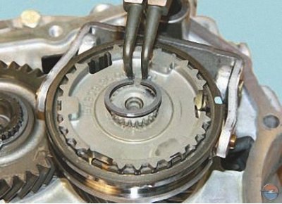
16. Remove the 5th gear synchronizer retaining ring.
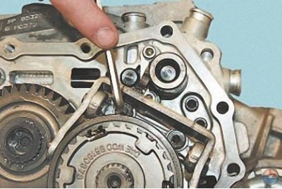
17. Remove the two bolts securing the 5th gear shift fork bracket…
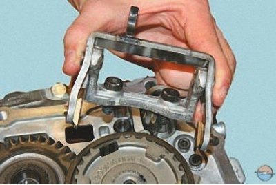
18. …and remove the bracket together with the fork.
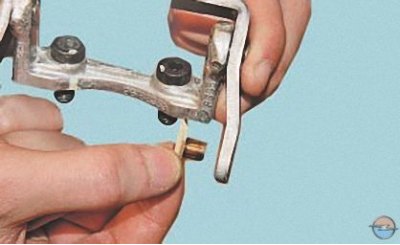
19. Remove the breadcrumbs from the fork.
Note: Replace worn crackers with new ones during assembly.
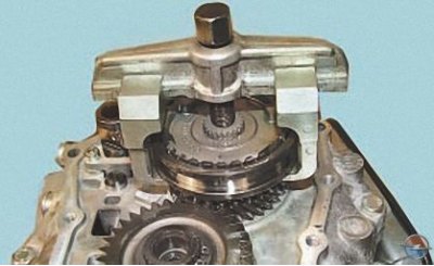
20. Install the universal puller on the 5th gear synchronizer sleeve…
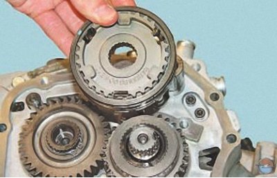
21. …and press the coupling assembly with the hub off the shaft.
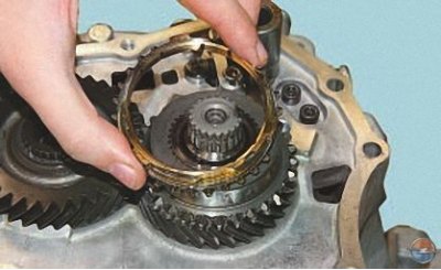
22. Remove the synchronizer locking ring…
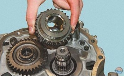
23. …driven gear of the 5th gear…
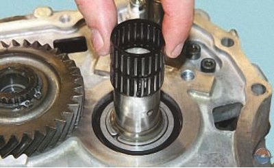
24. …and a needle bearing.
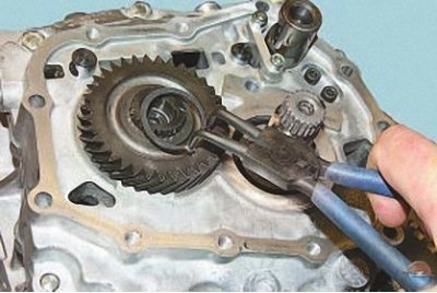
25. Remove the retaining ring of the 5th gear drive gear.
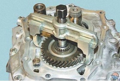
26. Install the universal puller on the V-gear pinion…
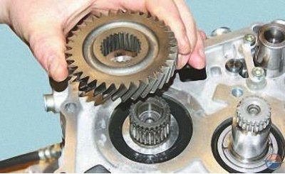
27. …and press the gear off the shaft.
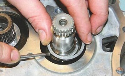
28. Remove the retaining ring from the secondary shaft…
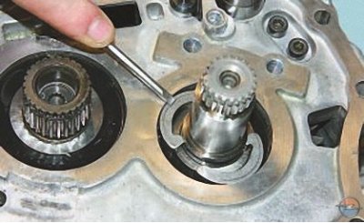
29. …and remove the two thrust half rings.
30. Remove the five bolts securing the intermediate housing to the gearbox housing…
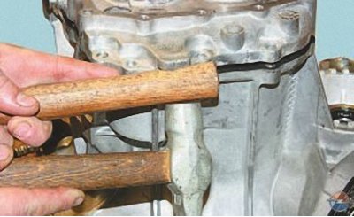
31. …separate the intermediate crankcase from the gearbox crankcase using hammer blows through a wooden spacer supported by a special crankcase lug…
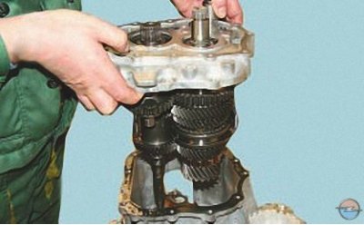
32. …and remove the intermediate crankcase together with the shafts.
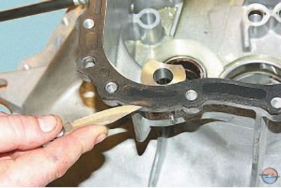
33. Remove the crankcase gasket by separating it with a sharp knife.
Note: Replace the intermediate case gasket with a new one each time the joint is disassembled, since a used compressed gasket may not provide a tight seal when reassembled.
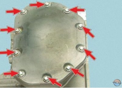
34. Unscrew the ten bolts securing the lower gearbox cover and remove the cover together with the gasket.
35. Separate the gasket from the cover.
Note: Replace the gearbox lower cover gasket with a new one each time the joint is disassembled, as a used compressed gasket may not provide a tight seal when reassembled.
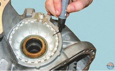
36. Mark the position of the differential bearing adjusting nut relative to the gearbox housing.
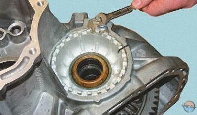
37. Unscrew the adjusting nut retainer bolt…
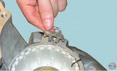
38. …remove the retainer…
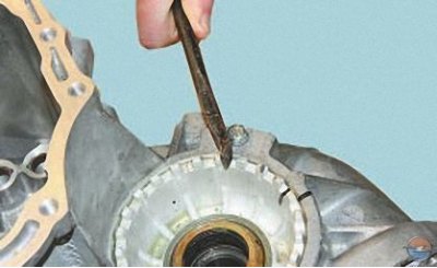
39. …move the adjusting nut from its place with a mounting blade, as shown in the photo…
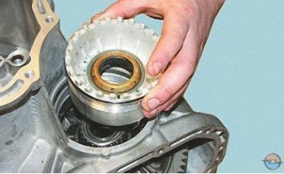
40. …and, having counted the number of turns, unscrew the nut.
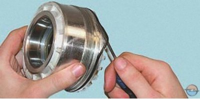
41. Remove the sealing ring from the nut.
Note: Replace a ring that is too compressed, hardened or torn.
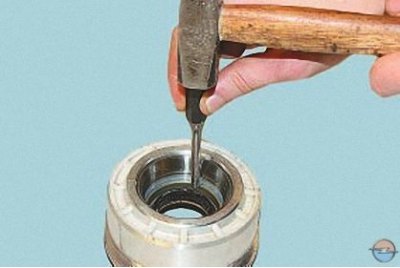
42. Press the axle shaft seal out of the nut.
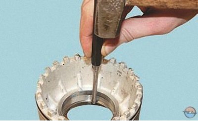
43. If it is necessary to replace the differential bearings, turn the adjusting nut over, place a couple of wooden blocks underneath and press the outer ring of the differential bearing out of the nut.
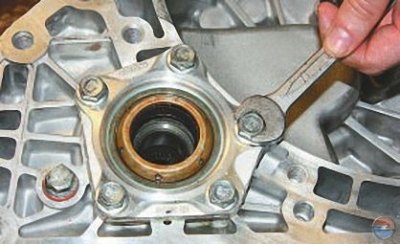
44. Remove the five bolts securing the right differential bearing cover…
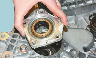
45. … remove the cover and the sealing ring from it, press the seal out of the cover and, if necessary, the outer bearing ring in the same way as you pressed them out of the adjusting nut.
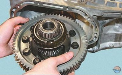
46. Remove the differential assembly from the gearbox housing.
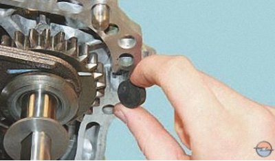
47. Remove the magnet from the crankcase…
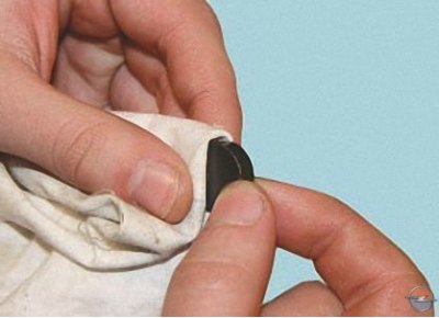
48. …and clean it from wear products.
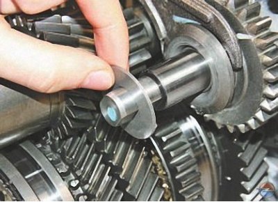
49. Remove the spacer washer from the reverse intermediate gear shaft.
Note: The reverse idler gear spacer may remain in the gearbox housing when separating the gearbox housing and the idler housing. Remove it from there.
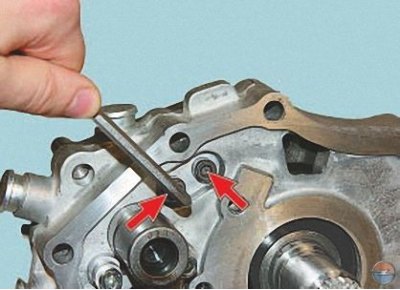
50. Remove the two bolts securing the pawl bracket…
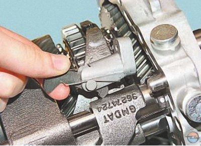
51. …set the fork rods sequentially to the II, V and III gear positions and remove the bracket together with the pawl.
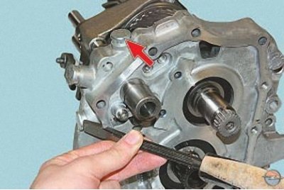
52. Using a hammer and a chisel with a blunt tip, knock out the plugs of the gear shift fork rod retainers…
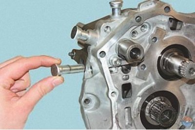
53. …and remove the clips.
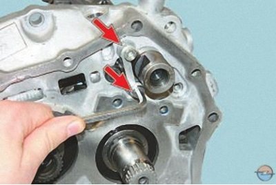
54. Remove the two screws securing the locking pin…
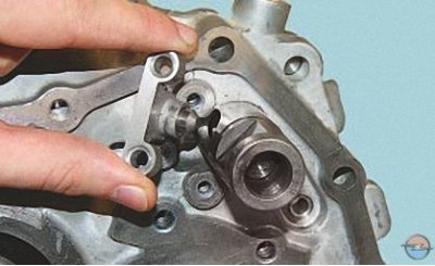
55. …remove the bracket…
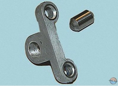
56. …and remove the pin from the bracket.
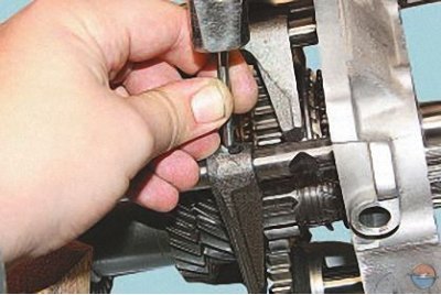
57. Resting the free end of the rod on a wooden block, knock out the pin securing the fork for engaging the reverse intermediate gear with a punch…
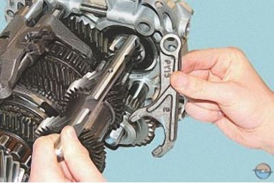
58. …and remove the stem and fork.
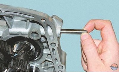
59. Remove the pin for locking the simultaneous engagement of two gears from the holes in the intermediate housing.
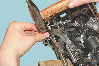
60. Knock out the pin securing the shift fork for III and IV gears…
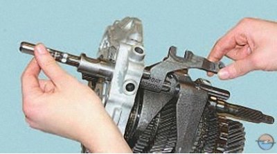
61. …remove the rod and remove the fork.
Note: The gear engagement clutches must be in neutral position when removing the fork.
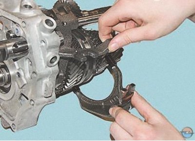
62. Lift the 5th gear engagement fork lever and remove the 3rd and 4th gear engagement fork.
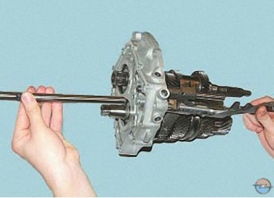
63. Remove the rod from the crankcase and remove the 5th gear engagement fork linkage.
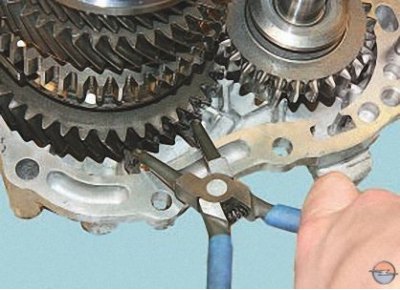
64. Internal snap ring pliers (working on compression) compress the secondary shaft bearing snap ring…
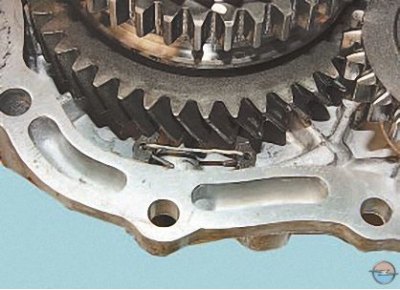
65. …and fix it in this position.
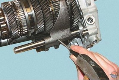
66. Knock out the pin securing the 1st and 2nd gear shift fork…
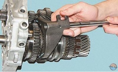
67. …remove the rod and remove the fork.
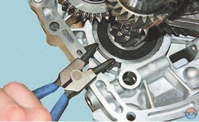
68. External snap ring pliers (working on decompression) loosen the primary shaft bearing retaining ring…
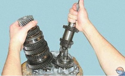
69. …and remove the primary and secondary shafts by extracting their ends from the intermediate crankcase.
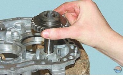
70. Remove the reverse intermediate gear.
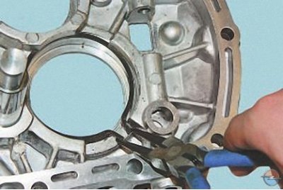
71. Using a puller, remove the primary shaft bearing retaining ring from the groove in the intermediate crankcase.
72. Before inspection and defect detection, thoroughly wash and dry the gearbox parts.
73. Inspect the gearbox housing, intermediate housing and rear cover. There should be no chips on them. There should be no nicks, scratches, dents, etc. on the mating surfaces. Remove minor damage with fine-grained sandpaper. In case of severe damage, replace the defective parts.
74. Check the bearing seats. There should be no signs of wear or damage on these surfaces. If there is damage, replace the housings.
75. Check the condition of the gear engagement rods. If the rods are bent or have burrs, nicks or wear on the dimples for the locking pins, replace the rods.
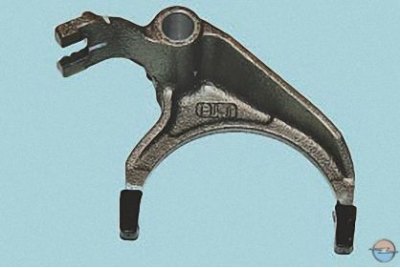
76. Check the condition of the gear shift forks. If they are bent or the tabs are worn, replace these parts.
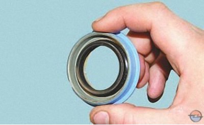
77. If oil leaks through the seals are detected during operation and their working edges are worn, the seals must be replaced.
78. Check the condition of the bearings. If you find cavities on the raceways and rolling elements, traces of indentation of the rolling elements on the raceways, or if the separators are damaged, the bearings must be replaced.
79. Replace the intermediate case, gearbox rear cover and gearshift mechanism gaskets.
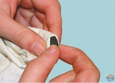
80. Clean the magnet from wear particles. If the magnet has cracks or its magnetic properties are weakened, replace the magnet.
Assemble the gearbox in the reverse order of disassembly, taking into account the following.
1. Before assembly, generously lubricate all rubbing parts with transmission oil.
2. Assemble all threaded connections using anaerobic thread locker.
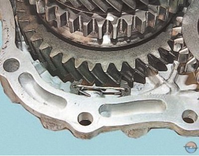
3. Before installing the secondary shaft into the intermediate crankcase, squeeze the retaining ring with round-nose pliers and secure it in the compressed state with wire. Remove the wire after installing the shaft into the crankcase, making sure that the ring enters the crankcase grooves without distortion.
4. When installing the differential, if its bearings were not changed, tighten the adjusting nut of its bearings by the same number of turns as when loosening, until the marks made during disassembly are aligned.
5. If the differential bearings have been replaced, after installing it, adjust the bearing preload according to the value of the bearing turning resistance moment by tightening or loosening the adjusting nut. For new bearings, the resistance moment should be 2 N·m (0.2 kgf·m) when the driven gear of the main transmission rotates at a speed of 1 rpm. If the bearings have not been replaced, the resistance moment should be 1 N·m (0.1 kgf·m).
6. Before installing the lower gearbox cover, lubricate its gasket with consistent grease.
Visitor comments