


2. Remove the upper and lower steering column cover panels (see Chapter 11).
3. Remove the exterior lighting switch panel from the left side of the steering column (see Chapter 12) and disconnect the electrical wiring connector.
4. Remove the left lower instrument panel trim cover and the side trim cover of the center console on the driver's footwell side and the air supply hose to the driver's footwell (see Chapter 11).
5. Using the steering wheel, turn the front wheels to the straight-ahead position, remove the key from the ignition switch and lock the steering column.
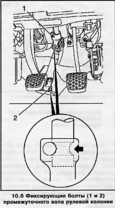
6. Remove the two fixing bolts (see accompanying illustration) intermediate shaft of the steering column - remember their installation position. Remove the shaft.
7. Disconnect the electrical wiring from the brake light switch sensor.
8. Unhook the return spring. Remove the bolt (see accompanying illustration) fastening the vacuum booster servo rod to the brake pedal and separate the rod.
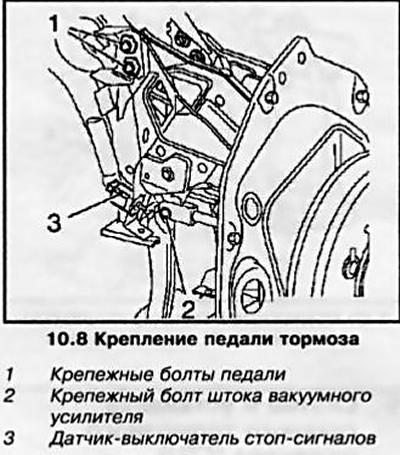
9. Remove the damper, unscrew the 2 mounting bolts and 4 nuts and remove the brake pedal together with the mounting bracket. If necessary, remove the brake light switch sensor from the pedal assembly.
10. Installation is performed in the reverse order of removal. After installing all components, check that the position of the steering wheel coincides with the straight-ahead direction of movement of the wheels. The fixing bolts of the intermediate shaft of the steering column must be lubricated with a fixing compound before installation.
Visitor comments